*** START OF THE PROJECT GUTENBERG EBOOK 54244 ***
[Illustration:
A SUB-SURFACE IRRIGATION SEWAGE-DISPOSAL PLANT.
_Sewage._ _Frontispiece._
]
Practical Methods of Sewage Disposal
FOR RESIDENCES, HOTELS AND INSTITUTIONS
BY
HENRY N. OGDEN
M. AM. SOC. C.E.
_Professor of Sanitary Engineering, Cornell University_
AND
H. BURDETT CLEVELAND
ASSOC. M. AM. SOC. C.E.
_Principal Assistant Engineer, New York State Department of Health_
_FIRST EDITION_
_FIRST THOUSAND_
NEW YORK
JOHN WILEY & SONS
LONDON: CHAPMAN & HALL, LIMITED
1912
Copyright, 1912, by
HENRY N. OGDEN
and
H. BURDETT CLEVELAND
PUBLISHERS PRINTING CO., 419–421 LAFAYETTE ST, NEW YORK
------------------------------------------------------------------------
CONTENTS
CHAPTER I. INTRODUCTORY
PAGES
The problem of sewage disposal. Composition and character of 1–13
sewage. Action of bacteria. Soils and their value for sewage
treatment. Three essential conditions for effective sewage
purification. Rates of operation. Preliminary and final
treatment.
CHAPTER II. THE SETTLING TANK
Function and capacity of settling tanks. Their construction. 14–36
Siphon chambers. Use of concrete. Pipe connections. Roof.
Baffle boards. Imhoff or Emscher tanks.
CHAPTER III. VALVES, SIPHONS, AND SIPHON CHAMBERS
Hand valves. Gate valves. Flap valves. Various types of 37–54
siphons. Alternating and plural siphons. Air-lock siphons.
Dosing apparatus.
CHAPTER IV. SUB-SURFACE IRRIGATION
Advantages of sub-surface irrigation for sewage disposal. 55–72
Details of system. Tables for use in constructing. Siphon
chambers. Sub-surface tile. Alternate use of separate
portions of area. Underdrainage.
CHAPTER V. SEWAGE FILTERS
Relative efficiency of various types. Sand Filters. Tables for 73–97
use in constructing siphons. Dosing and distribution methods.
Maintenance. Contact Beds. Methods of construction. Alternate
and timed siphons for filling and discharging. Table for use
in constructing. Sprinkling Filters. Their construction and
operation. Complicated and undesirable for small
installation.
CHAPTER VI. BROAD IRRIGATION
Fertilizing elements in sewage. Value of sewage for irrigation. 98–111
Area required for sewage irrigation. Methods of applying the
sewage. Maintenance of irrigated areas.
CHAPTER VII. ESTIMATES OF COST
Cost of material: of laying sewers and drains; of sand; of 112–128
excavating and refilling; of rock excavation; of concrete
work; of valves; of dosing devices; of filling material for
beds; of finishing and cleaning up. Table to show items to be
considered in estimate of cost.
LIST OF FIGURES
A sub-surface irrigation sewage-disposal plant _Frontispiece_
FIGURE PAGE
1. Plan of settling tank 15
2. Longitudinal section of settling tank 17
3. Sketch of settling tank with longitudinal 19
partition wall
4. Forms used for building side walls for concrete 23
tank
5. View of settling tank, showing baffles, sludge 26
pipe, drain pipe, and inlet and outlet pipes
6. Section showing tank with concrete roof and form 28
for constructing roof
7. Form for manhole opening 30
8. Plan and longitudinal section of modified Imhoff 33
tank
9. Vertical cross-section of modified Imhoff tank 34
10. Sludge valve for floor of tank 38
11. Sludge valve for side wall of tank 39
12. Sluice gate valve made by Coffin Valve Co 40
13. Ordinary gate valve 40
14. English slide valve with wedge-lock handle 41
15. Flap valve attached to length of sewer pipe 42
16. Flap valve with metallic seat attached 43
17. Flap valve with loose-link hinges 44
18. Intermittent dosing apparatus made by Ansonia 45
Manufacturing Co.
19. Simplest form of automatic siphon 46
20. Van Vranken automatic siphon 47
21. Miller automatic siphon 48
22. Double alternating siphons of the “Merritt” type 49
23. Triple alternating siphons of the Miller type 50
24. Single “Merritt” automatic siphon 51
25. Air-lock siphon for admitting and releasing 52
sewage from each one of four beds in regular
order
26. Plan and section of sub-surface irrigation system 61
27. Plan and section of a portion of a sub-surface 62
irrigation system
28. Y-branch of vitrified tile pipe 64
29. Eighth bend of vitrified tile pipe 64
30. Sub-surface tiling 65
31. Photograph of tile laid as if for sewage disposal 66
32. Sub-surface tiling with broken stone or gravel 67
surrounding pipe
33. Sub-surface systems on irregular ground 68
34. Special casting of double Y-branch with swinging 69
gate
35. Double Y-branch with valves on branches of main 70
carrier
36. Sub-surface tiling system with underdrains 71
37. View of sand-filter beds for village in 75
Massachusetts
38. Layout for intermittent sand filtration 78
39. Intermittent sand-filtration beds 79
40. Portion of distributing troughs for sand filters 80
41. General view of disposal plant at Bedford 81
Reformatory
42. View of sand filter with distribution trough. 82
Settling tank is at the end of the bed
43. View of diverting manhole 83
44. Plan of diverting manhole 84
45. Five-way diverting manhole 85
46. General plans of contact-bed system near Albany, 89
N. Y., opposite page
47. View of sprinkling filter at Dansville, Pa., in 95
winter
48. Distribution of sewage and arrangement of check 106
levees on a hillside
49. Distribution of sewage on a hillside of moderate 107
slope
50. Square beds for orchards according to some 108
Western practice
51. Grain-field in spring in process of irrigation 109
PRACTICAL METHODS OF
SEWAGE DISPOSAL
FOR
RESIDENCES, HOTELS AND INSTITUTIONS
CHAPTER I
INTRODUCTORY
The problem of sewage disposal for a single house differs from the
corresponding problem for a city chiefly in two ways: first, because in
the city it is becoming, if it has not, indeed, already become, a
necessity, and city authorities, though somewhat reluctantly, are
willing to grant the necessary appropriation to secure engineering
advice which will solve the problem in a scientific as well as economic
fashion. In the case of a single house, whether a farm-house or a villa,
the necessity of employing competent engineering advice has not been
generally recognized, and no attempt has been made to solve the problem
of sewage disposal in a scientific manner.
Cesspools have been considered the only way of caring for sewage in
places where a running stream was not available, or where attempts were
made to protect such a stream from pollution, and while, in these last
few years, crude attempts have been made to utilize the so-called septic
tank, such attempts have generally been so unintelligent that the
results have been anything but satisfactory. Since it has been
understood that insects, such as flies and mosquitoes, play an important
part in the transmission of disease, the danger of overflowing cesspools
and of open ditches in which stagnant sewage is present, has been
appreciated; also the higher standards of living which have made
themselves felt throughout the rural community have demanded in
farm-houses and country homes sanitary conveniences which have hitherto
been wanting.
Gradually every house is using more and more water for various purposes,
and living conditions, which in the past tolerated a scanty supply drawn
from a pump, are no longer endured. The increased water supply and the
demands of extended plumbing mean a greater amount of sewage—so great an
amount that, in many cases, soils which could receive and digest the
waste waters from houses supplied by wells are clogged and made
impervious by this greater amount.
Further, the danger to wells from the infiltration of cesspools is more
feared, and it is understood as never before that in order to maintain
the highest degree of health in a family the drinking-water used must be
above suspicion and not subject to contaminating influences in the
vicinity.
Again, communities are being aroused to the intrinsic value of
maintaining streams in a pure condition—partly because of the value of
fish and ice coming from the streams themselves, and partly on the broad
ground that watercourses belong to the country as a whole, and must be
kept pure for the sake of succeeding generations, not spoiled for them
on account of the selfishness of a few at the present time.
Thus it is that to-day the problem of sewage disposal, while arousing
general interest, is recognized as one which requires more than the
common sense of an average person, that the force and principles
involved are understood to be not those in common use, and that, for
successful disposal of sewage, special knowledge and judgment are
required.
Whatever the character of the sewage and whatever the kind of soil
available for treatment, the method of dealing with sewage most obvious
to most people has been to discharge the sewage directly into the
nearest watercourse. This has been the practice of cities as well as of
individual houses in the past, and the practice is very difficult to
check because of the economy of this method of disposal. In many cases
there is no objection to this method, and where a large stream is
available, where no use is made further downstream of the waters for
drinking purposes, and where the volume of water in the stream is
sufficient to dilute the sewage to a point where no odors or
objectionable appearances result, it would seem most uneconomical to
adopt any more complicated method of disposal than by simply carrying
the outfall pipe into the main bed of the stream.
In New York State, and in a number of other States, the number of which
is continually increasing, such direct discharge, however, is not
permitted by law except under certain conditions. In New York State it
is required that any house, butter or cheese factory, manufacturing
establishment, or village shall obtain the permission of the State
Commissioner of Health before such a method of discharge be adopted, and
in order to obtain this permission it must be definitely shown that the
conditions of the stream are such that no reasonable objection to this
method could be urged. The policy of the various Departments of Health
in the United States is gradually becoming more and more rigorous in the
matter of prohibiting the discharge of crude sewage into watercourses,
and it is wise to make very sure that the discharge of sewage into
streams is above the suspicion of a nuisance before adopting this as a
suitable method. Rather would it seem better to provide for some method
of treatment and allow only purified sewage to go into the stream than
to run the risk of being forced in a few years to reconstruct the entire
line of outfall pipe, with perhaps an entire reconstruction of the
plumbing within the house.
The problem of treatment is the question of so modifying the character
of a large volume of dirty water that it shall neither injure the
quality of any drinking-water into which it may be discharged, nor cause
objectionable odors, nor present disagreeable appearances in any body of
water into which it may be emptied.
In order to properly understand a reasonable method of treatment some
consideration must be given to the composition of sewage. This is
chiefly water with which is mixed a small amount of animal, vegetable,
and mineral matter. Roughly speaking, the amount of mineral dirt is
about one tablespoonful to a barrelful of water, and the combined amount
of animal and vegetable matter amounts to another tablespoonful. It
seems almost impossible that so small a quantity of organic matter as
one tablespoonful in a barrel of water could cause offense in any way,
and yet engineers, city officials, and householders know by bitter
experience that, when spread out on the surface of the ground or when
allowed to stand in pools, water so polluted will undergo putrefaction
resulting in most disagreeable odors and in complete stagnation. The
problem of sewage treatment, then, consists in removing from the
barrelful of water, the tablespoonful of organic dirt, whether animal or
vegetable, in such a way that no odors shall be occasioned by the
process and at the same time so that the cost of the process may be a
reasonable one.
Unfortunately, the greater part of this organic matter is in solution,
dissolved, like salt in water, so that, though undeniably present, it
must be removed by some process more complicated and less obvious than
that of simple straining. It would be comparatively simple if the
polluting substances remained floating or suspended in the water. Then
they could be strained out through a fine sieve or settled out in a
tank, either with or without the aid of chemicals. But for particles in
solution, straining, by itself, is useless and, while in large plants
frequent use is made of sieves as a complement to the main process of
purification, in small plants it is of so little value as hardly to
deserve consideration.
Another factor enters to lessen the value of the use of screens or
sieves in an installation for a single house. A great deal of the
organic matter found in sewers requires both agitation and time for its
subdivision into particles small enough to be acted upon in any process
of purification adopted. If a screen is used, large particles of
putrescible matter are held on the screen since not enough time has
existed to break down their mass, and thus the screen itself becomes a
most emphatic disturbance and a most objectionable feature of the
purification plant.
For efficient purification, therefore, some method of reducing and
modifying the character of organic solids, particularly those in
solution, must be selected. In seeking a method by which this may be
accomplished, scientific men found years ago that this very process was
being carried on continually by natural forces, although at a very slow
rate of purification. All organic matter, however formed and wherever
present, is subject to the natural forces of decay. Fruits, vegetables,
and meats of all kinds, exposed to the air, rapidly lose their original
character and form and in the course of time disappear entirely. Except
for this provision of nature, the accumulation of organic wastes since
the beginning of the earth’s occupation by human beings would be so
great that the earth would be uninhabitable on account of the deposits
of waste matter which would have formed by this time. Nature, then,
recognizes the need of disposing of organic wastes, and her method is
the one which apparently must be followed by human beings if successful
treatment is to be secured.
Only a few decades ago, it was found that this process of decay was due
to the activity of very small organisms known as bacteria, and their
agency was proved by experiments which showed that if vegetables or meat
were kept free from bacteria, no decay, fermentation, or putrefaction
took place. It was proved that the air itself was not responsible
because in certain experiments air was allowed to enter through a
filtering medium fine enough to strain out the bacteria and no decay
took place, although oxygen and air were both freely admitted. It is
well understood by the housewife that fruits can be kept indefinitely if
they are cooked sufficiently to kill any bacteria present and then
sealed in bacteria-free, air-tight jars. When such preserves spoil, it
is because some bacteria were left in the jar or have since been
admitted through an imperfect top. When decay is allowed to proceed, the
obvious result is, first of all, a softening of the material, as in the
case of a rotten apple, a liquefaction, as it is more technically known.
Following that part of the process is a gradual breaking down of the
material, the residue being of an earthy character which is assimilated
by the soil into which it falls.
The bacteria required for the putrefaction of organic matter are among
the most widely distributed of all the micro-organisms. They are always
found in the air, except on mountain tops, in deserts, and over the
ocean. They are very numerous in surface waters, such as streams and
ponds, and their relative number everywhere increases as the amount of
organic matter increases, so that the greater the need for them the
greater is their number. It has been found that the great majority of
these bacteria require air for their energetic development, and this
fact is most important when it comes to the practical construction of a
piece of apparatus for making use of these bacteria. It has also been
found that, for several reasons, these bacteria work most effectively in
the soil and can take care of a larger quantity of organic matter there
than elsewhere. This is partly because in the surface layers of the
soil, particularly where that soil has been cultivated, a great number
of the particular bacteria involved in decay are always to be found.
Pure, clean sand from the desert contains almost none of these
beneficent bacteria. Rich garden soil is fairly teeming with them, so
that, curiously, the more organic matter and the more bacteria present
in any soil, the more active that soil will be in taking care of other
organic matter.
Then, again, the soil particles, particularly in sandy soil, are so
separated as to allow between them a certain and appreciable amount of
air, and by means of this air the activity of the bacteria is made
continuous and the products of their activity utilized. Without such an
admission of air, the bacteria are choked and diminish rapidly in
numbers. There is, however, a definite degree of purification and a
certain quantity of organic matter which can be taken care of by the
bacteria incident to any particular soil. Up to that quantity
purification proceeds more or less satisfactorily according to the
intelligence shown in feeding the bacteria in such a way as suits their
convenience. If, however, that quantity be exceeded, all purification
stops, the bacteria are apparently discouraged, and no further
improvements can be expected. A fine-grained soil will not be so useful
as a coarse-grained soil because the former does not allow sufficient
air in the interstices of its soil particles. Another practical reason
for not making use of soils of fine grains is that such soils can absorb
only a small amount of liquid because of the mechanical construction of
the material. On the other hand, soils whose grains are too coarse are
undesirable because their mechanical construction is such that the
liquids containing organic matter in solution pass through so rapidly
that time enough is not given for bacterial action.
As a result of the principles just enumerated, it may be said that there
are three distinct and essential conditions for the successful disposal
of sewage through the soil. These three conditions are, first, a rate of
application suitable to the soil which it is proposed to use; second, an
interrupted or intermittent delivery of the sewage so that the bacteria
can obtain, between consecutive doses of sewage, the necessary amount of
oxygen for their own preservation and well-being; and, third, a resting
period in which is carried forward that intimate association between the
partly decomposed organic matter and the oxygen or air present in the
pores of the soil by which the final oxidation is obtained.
The rate of application varies, as already indicated, with the size of
particles found in the soil, and it should also vary with the
purification desired. The larger the particles, the higher may be the
rate of application, but less efficient will be the process. With grains
of sand as fine as 1/200 of an inch, and with a rate of application not
greater than five gallons per square yard of surface per day, filtration
through such an area has been proved to be capable of removing from the
foulest sewage all the objectionable material and converting the liquid
into what is an equivalent of the purest spring water. If the rate
appropriate to this particular soil is exceeded, the efficiency
decreases, and the unmistakable and inevitable result is to stop all
purification and convert the filter into a stagnant cesspool. If, to
take the other extreme, the soil particles are increased until they are
as large as hen’s eggs, then, if the rate of application is not greater
than 200 gallons per square yard of surface per day, and if the method
and rate of application are suitable to this large amount, the resulting
effluent is sufficiently freed from its objectionable matter so that the
liquid can be turned into any body of water without danger of odors or
other nuisance. If this rate is exceeded, or if the method of
application is not carefully considered, the resulting effluent is foul
in the extreme and the process itself becomes a nuisance.
It can be seen by this brief explanation that it is not possible to
assign any particular rate of application to any particular kind of
treatment, since in all the methods of purification which have been
worked out considerable variation in the details of that particular
method have been practised. It will be possible, therefore, in
succeeding chapters to indicate by the size of filters recommended only
limiting or average values for rates of purification, since those rates
are always dependent upon other factors than the particular method being
discussed. It must also be remembered that soils may exist which have no
porosity whatever, and through which it is impossible for sewage to make
its way. Such soils are not available for sewage purification, and, no
matter how small the rate or how careful the method of application, such
areas will fail to produce any practical purification. Soils like clay,
peat, and fine water-deposited silt are of this sort. Clay soils may
sometimes become pulverized by cultivation so that they will ultimately
be able to take care of a moderate amount of sewage. In such a case it
is possible to dispose of sewage successfully in the top six inches of
soil which, by continual cultivation, has been made out of the stiff
clay. In such cases, the difficulty is not that of oxidizing the sewage,
but that of taking care of the effluent, which must be held between the
cultivated soil and the raw clay underneath.
The second requirement mentioned is secured by discharging the sewage
onto the soil area at intervals, the number of doses per day depending
upon the size of particles in the bed. There has been a general
principle established that the size of these doses ought to be smaller
as the size of the particles increases, so that, whereas in the case of
sand beds the total daily dose is usually divided into from one to three
parts and each part delivered onto the bed with an appropriate interval,
in the case of coarser materials used for sprinkling filters, the time
interval between doses is much reduced and in some installations
recently constructed in England that interval has been measured in
seconds. The variations in the rate of flow of sewage onto any filter,
however, are so great that any such requirement as designing discharging
apparatus to work at intervals of a few seconds is useless, and if as
small an interval as one minute is provided for the coarsest material
for the maximum rate of flow at any time of the day, the installation
will probably be successful for the lesser rates occurring at other
times of the day. As an indication of the way in which this modification
is made, it is customary, when the size of soil particles is that of
peas, to make the interval between successive discharges about one hour,
so that the dose applied at any one time would be equal to 1/24 of the
daily volume. With gravel filling, the particles being the size of
English walnuts, the interval between doses is shortened to five
minutes, and the amount of any one dose is thus made 1 about 1/280 of
the total daily volume. With the coarser filling, as when a size as
large as hen’s eggs is used, the interval would be cut down to about one
minute. It should be added that the intervals last mentioned are
characteristic only of some devices used for dosing sprinkling filters
and that there is a wide divergence of practice among engineers when
dealing with any particular size of sand or stone particles in all kinds
of filter beds.
The third requirement, namely, the occasional resting of the bed, is met
by providing some additional area over that theoretically required, so
that the flow may be diverted from part to part of the total area (which
is usually divided into beds for this purpose), and in this way each
part is allowed, in turn, a period for resting. For example, if the
required area be divided into two beds and a third bed added equal in
area to one of the two and a regular rotation of dosing be practised,
each bed would rest not only the time between the regular twelve-hour
period dosing, but might also be given a complete rest, occasionally,
for an extended period. This third requirement is probably less
imperative with the coarser particles and there are many examples of
coarse-grained beds which have been continuously operated for a period
of years. It is found, however, that with such treatment clogging is
inevitable, and that such clogging is partially relieved by a period of
rest somewhat proportional to the length of time the beds have been
operated. It is, then, only shortsighted policy to economize at the
beginning and attempt to save money by not building an additional area,
since the clogging of the whole plant is bound to occur in the course of
time, and then another plant must be built or the material forming the
bed taken out, washed, and replaced. Otherwise the sewage must go
unpurified to the outfall while the bed is recovering from the long
period of overwork.
It is convenient to divide sewage purification into two processes, the
preliminary process and the final, or finishing process, and, while the
preliminary process, in itself, never accomplishes purification, yet it
is of considerable value in facilitating and increasing the rate and
efficiency of that purification. The most common preliminary treatment
is sedimentation, by which the larger solids in suspension are allowed
to settle in a tank or tanks so that the filter beds later used are
relieved from the accumulation of those deposits. Under the name of
septic tank such a receptacle for suspended solids has been exploited as
a complete method of purification, and many underground tanks have been
constructed in various parts of the country which have, at the time of
their installation, been considered competent to furnish all the
necessary purification. When it is remembered that less than one-half of
the organic matter in sewage is in suspension and that the best results
in any sort of a tank succeed in depositing only one-half of those
suspended solids, it can readily be seen that a tank, whether called
septic or settling, cannot be a complete method of treatment. In
reality, such a tank does little more than take out from the sewage the
greasy material and a certain proportion of the suspended matter.
Whatever part of this is organic matter may, by a particular arrangement
of the tank, be considerably reduced in quantity, so that the intervals
of cleaning can be extended, but in every tank the removal of the
deposits is necessary, and subsequent treatment is required if adequate
purification is accomplished.
The final, or finishing, process may be carried out according to any one
of several methods. It may be done by discharging the tank effluent into
a system of agricultural drains laid just below the surface of the
ground, called sub-surface irrigation. It may be done by removing the
top soil from a bed of sand placed by nature, and needing little except
suitable surface distribution to insure the most efficient purification.
For a small plant, instead of a sand filter, for which the sand is found
naturally in a suitable location, an artificial filter may be built by
preparing an enclosure and carting in sand for filling.
Where no sand is available, or where its use would be uneconomical,
broken stone may be used to ensure final treatment. With stone, on
account of its large voids, the enclosure must either be water-tight,
and the outlet pipe must be provided with a valve or other device so
that the sewage under treatment may be held in the enclosure or tank
long enough to deposit the solids in suspension and to be acted on by
the bacteria concerned. This method is known as the contact bed
treatment. Or, finally, the desired results may be obtained by spraying
the sewage onto a deep layer of broken stone, the method being called
the sprinkling filter treatment.
The choice of the final treatment, in any particular case, depends on
the character and slope of the ground, on the availability and cost of
sand or of broken stone, and on the amount of sewage to be treated. It
is hoped that the following pages will give to the reader both an
intelligent appreciation of the advantages and disadvantages of each of
the several methods of sewage purification discussed, and also
sufficient insight into the necessary details of construction so that
the method chosen can be put into successful operation.
CHAPTER II
THE SETTLING TANK AND ITS CONSTRUCTION
As has been stated, a most effective preliminary step in the treatment
of sewage is to pass it through a properly designed settling tank in
order that the grosser solids and suspended matters as far as possible
may be deposited there and finally disposed of separately from the
liquid sewage. This partial removal of the suspended matters, amounting
to about fifty per cent. in well-designed and carefully operated tanks,
very materially aids in the final treatment of sewage on filters or on
sub-surface irrigation areas by preventing clogging of the filters or of
the piping in the irrigation system.
In connection with the larger settling tanks for hotels or institutions,
it is sometimes advisable to pass the sewage first through a screen
chamber before it is discharged into the settling tank, in order that
the grosser suspended solids may be collected more easily than from the
tank; but, as has been pointed out, screening of sewage is not necessary
at small disposal plants, and in fact is not generally advisable owing
to the continual labor involved in removing and disposing of the
screenings, and no description of screening plants will therefore be
given.
The old method of discharging sewage and house wastes into loose-walled
cesspools on all occasions and under all sorts of conditions is rapidly
changing, as is desirable. True, in certain locations, where ample area
is available, where the soil is dry and porous, and where neither
springs nor wells nor the soil near dwellings will be contaminated
thereby, cesspools may be safely used. In other locations a small
expenditure of time and money will provide the means by which nature’s
processes of reduction of the organic matter in sewage may be carried on
much more efficiently and satisfactorily than ever can be the case in a
cesspool.
[Illustration: FIG. 1.—Plan of Settling Tank.]
The scheme for properly disposing of sewage at any point should
therefore include its sedimentation in a settling tank of proper
construction and ample capacity, whether its final treatment is to be
effected by sub-surface irrigation, intermittent sand filtration,
contact beds, or sprinkling filters. Where the sewage effluent is to be
discharged into a stream or body of water of comparatively large flow or
volume, and where that stream is not subsequently used as a potable
water supply, it is sometimes permissible to subject the sewage to
settling tank treatment only. Such partial treatment, however, should be
arranged for only as a temporary measure, and the tank should be so
constructed with respect to the elevation of adjacent areas that works
for final treatment of sewage, when required, may be constructed as
advantageously as possible. Moreover, in the more progressive States, as
noted in Chapter I, the purity of streams is being carefully
safeguarded, and the general tendency of public health officials is to
require more complete treatment of sewage before its discharge into a
watercourse than is accomplished by settling tanks.
The settling tank for residences and institutions, as shown in Fig. 1,
should have a capacity of from five to fifteen cubic feet for each
person served by the sewer in order that proper time of detention in the
tank may be allowed for the sedimentation of the suspended matters in
the sewage. The depth of the tank should be from five to eight feet, and
its width should generally be from one-third to one-half the length.
Fig. 2 shows a longitudinal section of the settling tank and siphon
chamber.
[Illustration: FIG. 2.—Longitudinal Section of Settling Tank.]
The following table gives the dimensions of tanks which should be
adopted to provide a proper time of detention of sewage, based on the
number of persons to be served:
TABLE I
DIMENSIONS FOR SETTLING TANKS
══════════════════════════════════════╤══════════╤══════════╤══════════
Persons Served by Sewer. │ Mean │ Mean │ Depth
│ Inside │ Inside │(Feet).[1]
│ Width │ Length │
│ (Feet). │ (Feet). │
──────────────────────────────────────┼──────────┼──────────┼──────────
4 │3 │ 4 │ 5
8 │3 │ 7 │ 5
12 │4 │ 7.5 │ 5
15 │4 │ 8 │ 5
25 │4 │10 │ 5
35 │4.5 │12 │ 5
50 │6 │12 │ 5
75 │6 │15 │ 6
100 │7 │17 │ 6
125 │8 │17.5 │ 6
150 │8 │18 │ 6
175 │8 │20 │ 6
200 │8 │22 │ 6
250 –-2 compartments in tank, each │5.5 │18 │ 6
300 –-2 compartments in tank, each │5.5 │18.5 │ 7
350 –-2 compartments in tank, each │6 │19 │ 7
400 –-2 compartments in tank, each │6 │19 │ 8
450 –-2 compartments in tank, each │6 │22 │ 8
500 –-2 compartments in tank, each │6 │24 │ 8
──────────────────────────────────────┴──────────┴──────────┴──────────
Footnote 1:
12 inches greater than depth of sewage.
[Illustration: FIG. 3.—Sketch of Settling Tank with Longitudinal
Partition Wall.]
The dimensions of settling tanks given above provide for longer periods
of detention in the case of the smaller tanks than in that of the
larger, an excess which is necessary on account of the greater
fluctuation in the flow of sewage reaching the smaller tanks. The larger
tanks may be better and more conveniently operated if they are divided
by a longitudinal partition wall as shown by Fig. 3, and arranged for in
the table for tanks serving 250 or more persons. This provision is not
so necessary in the case of the smaller tanks, especially if they are to
be installed at summer resorts or country homes occupied for only a few
months in the summer. If, however, the tanks are to be operated
continuously they may have two chambers for greater convenience in
removing sludge. The flow through one compartment may then be stopped by
closing a valve placed on the inlet pipe to that compartment, or by
inserting one of the stop-planks or sluices in a diverting chamber, as
shown in Fig. 3, at the left of the tank and inserting a ten-inch board
in the groove over the outlet weir wall of the compartment to be
cleaned. The entire flow of sewage is then passed through the other
compartment while the first is being cleaned. This division of the tank
into two compartments is sometimes desirable in the case of the smaller
tanks and may easily be accomplished. For instance, instead of a tank 6
feet by 12 feet, two compartments may be arranged for, each 3 feet 6
inches by 10 feet; and instead of a tank 8 feet by 20 feet, two
compartments may be constructed, each 5 feet wide and 16 feet long.
The settling tank should be located as far as conveniently possible from
the dwelling, and especially from any wells or springs, in order that
leakage of sewage, which may always occur, will not lead to the
contamination of a water supply or of the soil near the residence. It
may not be possible in every case to locate such tanks more than fifty
feet away from the house or from the well, but the distance should never
be less than this, and when located at this minimum distance from the
dwelling or from a well, especial care should be used to make the tank
water-tight.
The walls of the tank should preferably be constructed of concrete,
although they may be built of brick or wood. The last material is often
the cheapest, and tanks constructed of lumber will last for several
years without renewal. The concrete tank, however, is more easily made
water-tight, and is a permanent structure. The walls of the tank, when
the height is less than 8 or 10 feet, should be 8 inches thick at the
top, and should have a batter on the inside of 1½ inches per foot of
height. If the tank is to be built with two compartments, the partition
wall should be 10 or 12 inches thick at the top and should have a batter
on both sides.
The tank should generally be placed with its top at the level of the
ground surface, and the sewer from the house should enter the end of the
tank with its flow line or invert 12 inches below the top of the walls.
The house sewer or drain should have a grade or fall of not less than 9
inches in 100 feet. Preferably, the sewer should be laid at the above
minimum grade for at least 50 feet or so before it enters the tank in
order to prevent excessive velocity in the sewage flow at this point. At
the entrance to the tank the sewer should be provided with an elbow so
that the sewage will be discharged downward below the surface.
Similarly, if an outlet pipe from the tank is used, as shown in Fig. 5,
this pipe should pass through the wall at the outlet end of the tank,
one foot below the top of the tank, and should also be provided with an
elbow which will start from below the surface.
Where a siphon is to be used to discharge the effluent from the tank
onto a filter or into a system of sub-surface tiling, the separate
chamber in which the siphon must be placed may be built as an extension
of the settling tank so that the end wall of the settling tank will
serve as one of the walls of the siphon chamber.
The siphon chamber floor may be placed considerably above the level of
the floor of the tank as shown in Figs. 2 and 3, since a sufficiently
large quantity of effluent for dosing a filter or a sub-surface
irrigation system may be collected in the chamber of reduced depth thus
provided. This shallower construction saves excavation and also reduces
the operating head or fall, which latter is sometimes hardly equal to
the demands of the subsequent treatment. The capacity needed in this
chamber for different installations will be given later in the
discussion of sewage filters and sub-surface irrigation systems.
Having determined upon the dimensions of the tank and selected the site,
the construction is commenced by making the excavation about four feet
wider and longer than the outside dimensions of the tank and siphon
chamber combined, in order to provide room for setting the forms for
placing the concrete, provided concrete is to be used in its
construction. With brick walls an additional width and length of two
feet is needed.
Fig. 4 gives an illustration of the forms to be used in constructing the
walls for concrete tanks, the cut at the left showing a view of the form
to be used when the tank is constructed either partly or wholly above
the natural ground surface, or below the surface in loose soils, and the
cut at the right showing a view of the form to be used when excavation
for the tank is made in rock, hardpan, or clay. The top width of the
walls should be 8 inches, and the bottom width should be 8 inches plus
1½ inches for each foot of height. Thus, for a wall 6 feet high the
bottom width should be 17 inches,—the inside face of the wall having a
batter of 1½ inches per foot of height. This batter is necessary, when
the tank is constructed below the ground surface, to withstand the
lateral earth pressure when the tank is empty. If the tank is to be
constructed above the ground surface, the outside wall should be
battered and the inside wall made vertical, since the pressure which the
wall must withstand is then only from the liquid within the tank. The
partition wall between the settling tank and siphon chamber should be 10
or 12 inches thick at the top, depending on its height, and should have
a batter on both sides.
[Illustration: FIG. 4.—Forms Used for Building Side Walls for Concrete
Tank.]
To set up the forms for the concrete walls, stakes 2 inches by 4 inches
and about 2½ feet long are first driven on each side of the bottom of
the wall, and 6 inches away from the wall as laid out, at intervals of 2
feet. Pieces of scantling, 2 inches by 4 inches and with a length equal
to the height of the wall, are then placed in upright position and
securely nailed to these stakes. The inner scantling are then inclined
and temporarily fastened at the top by a short nailing piece to the
outer row so as to leave an opening of 10 inches between each pair of
scantling. Additional stakes are then driven from 2 to 4 feet from the
wall on each side, as shown in the illustration, and braces 2 inches
thick and 3 inches or 4 inches wide are nailed to these stakes and to
the upright and inclined scantling. One-inch boards are then lightly
nailed to the scantling, as shown, the boards making up the inside face
of the form being placed in sections of two feet in order to afford
opportunity for thorough tamping of the concrete as the form is being
filled. The concrete is then placed between the boarded sides of the
form in 6–inch layers and well rammed.
The concrete should be composed of one part by measure of Portland
cement to two and a half parts of clean, sharp building sand and five
parts of broken stone or clean gravel. The cement and sand should first
be thoroughly mixed, while dry, to an even color and then wet and
tempered to a soft mortar. The broken stone or gravel, after having
first been thoroughly wet, should be spread evenly over the batch of
mortar and the mass shoveled over at least three times to insure a
thorough coating of the stones with mortar. The concrete thus made may
then be placed in the forms in six-inch depths and thoroughly rammed
until water covers the surface.
When it is essential that the tank be water-tight, and, in fact, in
constructing all tanks, each layer of concrete should be placed between
the forms, when possible, before the concrete in the layer previously
placed has set. If the work of placing the concrete is of necessity
interrupted, before placing another layer the surface of the older
concrete should first be sprinkled and swept with a stiff broom and a
thin coating of neat cement mortar (containing no sand) should then be
washed over the surface of the concrete.
It may be noted that a barrel of Portland cement (equal to four bags)
contains 3.8 cubic feet, so for concrete with the proportions of cement,
sand, and stone as specified above, for each barrel of cement used there
should be used 9.5 cubic feet of loose sand and 19 cubic feet of loose
stone; and for each cubic yard of concrete required there will be needed
1.30 barrels (or 5.2 bags) of cement, 0.46 cubic yards of sand, and 0.92
cubic yards of stone if the stone is fairly uniform in size and contains
forty-five per cent. of voids. With stone or gravel less uniform in
size, less cement and sand is required. The cement and sand, made into
mortar, will fill the voids or open spaces in the mass of broken stone.
(For further details see Chapter VII.)
As shown in the illustration (Fig. 4), the foot of each upright and
inclined scantling should be placed at the proposed elevation of the
floor of the tank, and the boarding should not be carried below this
level. Then, if the excavation for the wall has been carried to a level
6 or 8 inches lower than the floor of the tank, the concrete when being
placed between the forms will spread under the bottom of the forms,
making a footing for the wall on the outside and better insuring a
water-tight joint when the floor is laid against the inside foot of the
walls.
In making the excavation for the tank, after reaching the proposed level
for the floor a trench should be cut around the floor space to a depth
of 6 to 8 inches below the floor level. The width of this trench should
be such as to extend from 6 to 8 inches inside and an equal distance
outside the wall at the floor level. After the walls have been
constructed as described, the forms should be left in place for at least
24 hours, to allow the concrete to set, and then removed. The excavation
inside the walls should then be carried 6 inches below the floor level,
the soil well tamped, and a 6–inch layer of concrete placed to form the
floor of the tank. It is well to sprinkle all concrete daily until it
has thoroughly set.
If the type of siphon selected has a U-shaped pipe extending below the
floor of the siphon chamber, it will be necessary to set the siphon in
position while the floor is being laid and the discharge pipe in
position while the wall is being laid. The siphon should be so placed
that the bottom of the bell over the longer leg is 3 inches above the
floor of the siphon chamber or of the sump in the siphon chamber if such
a depression is made in the construction of the floor.
[Illustration: FIG. 5.—View of Settling Tank, Showing Baffles, Sludge
Pipe, Drain Pipe, and Inlet and Outlet Pipes.]
The floor of the tank should slope toward the inlet end at a rate of
one-half inch per foot of length in order to facilitate the removal of
sludge when the tank is being cleaned. This will result in providing a
somewhat greater depth at the inlet end of the tank than is shown by the
tables, and a lesser depth at the outlet end, leaving the depth at the
centre of the tank as shown. The inlet and outlet pipes to the tank,
which should be of cast iron, should be placed in position through the
forms while the walls are being laid.
When it is desired to have an outlet pipe from the tank near the bottom
(see pipe A, Fig. 5), for the purpose of drawing off the supernatant
liquid, and so saving the labor of removing the liquid by pail when the
tank is being cleaned, this pipe should be of cast iron, 4 inches in
diameter and fitted with a valve and valve rod placed outside the tank,
and should also be placed in position during the construction of the
tank. The valve rod, or stem, should reach to the surface of the ground
through a 3–inch pipe casing. The lower outlet pipe should be extended
around the siphon chamber to discharge into the effluent pipe leading
away from this chamber, when possible. This lower outlet pipe should
leave the tank at least one foot above the floor and sometimes at a
higher elevation, in order to discharge into the sewer leading to the
irrigation field or to the filter.
Pipe B in Fig. 5 shows a sludge pipe which may be laid to a suitable
site for disposing of sludge from the tank when the slope of the land
will permit the draining of the sludge by gravity into trenches or onto
a sludge bed. This sludge pipe should be fitted with a valve and valve
stem, and the valve may be inside the tank, as shown in the
illustration, or outside the tank, as shown on pipe A. If such an
arrangement for disposing of sludge is possible, it is manifestly
unnecessary to provide pipe A as shown in Fig. 5, since the supernatant
liquid as well as the sludge may then be piped to a sludge bed or pit.
This bed should be shallow, but of ample capacity to hold the entire
contents of the settling tank. The sludge may then be drawn off about
every six weeks, thereby operating the tank as a settling tank rather
than as a septic tank. It will be found after scum of a certain
thickness has formed on the surface of the sewage in the tank that the
thickness will not materially increase.
The roof of the tank should preferably be of concrete reënforced with
iron rods, although it may be of brick arches or of two-inch planking.
The use of brick for the roof is not advisable, however, since the forms
for the construction of the arches are rather difficult to make, and
brick roofs are apt to be broken down sooner or later through the action
of frost. A wooden roof, also, must be renewed at intervals and is not
as satisfactory as a concrete roof.
[Illustration: FIG. 6.—Section Showing Tank with Concrete Roof and with
Form for Constructing Roof.]
A section of a tank with a concrete roof is shown by Fig. 6, together
with the temporary form built up inside the tank on which to lay the
roof. The form is built by setting 2–inch by 4–inch scantling on wedges
along the walls of the tank in pairs 18 inches apart and bracing these
at the foot. Boards 1½ inches thick and 10 inches wide are then nailed
across the tank to the tops of the scantling, the top edges of the
boards being 1 inch below the top of the walls. A false roof is then
made of boards nailed lengthwise of the tank to the 10–inch boards, and
a layer of concrete 2 inches thick is then placed on the floor thus
made, reaching over the top of the walls to the outside edges. Iron
rods, ¾ of an inch thick and spaced 1 foot apart, are then placed on the
concrete across the tank and reaching to within 1 inch of the outside
edges of the walls. More concrete is then placed over the first layer to
a total depth of 6 inches or 8 inches, depending on the width of the
tank, the concrete being well rammed as it is placed. After the concrete
has set, the wedges may be knocked from under the upright scantling and
the form taken down and removed through the manhole. The manhole covers
and frames, as shown in the illustrations in Chapter III, may be cast at
local foundries or purchased through sewer-pipe dealers.
To provide manholes or openings through the roof into the tank and into
the siphon chamber, round openings 2 feet in diameter should be cut in
the false roof while it is being laid, the distance between the pairs of
scantling at this point being made 2 feet. The manhole frames should
then be so placed that the flange or base of the frame will be imbedded
to a depth of 2 inches in the roof when completed. The manhole at the
entrance end of the tank should be located at one side of the entrance
pipe and over the valve on the sludge pipe. To provide the necessary
opening through the concrete roof below the manhole frame, an
eight-sided wooden form, as shown in Fig. 7, with an inner diameter of 2
feet and a height equal to 2½ inches less than the thickness of the
roof, is placed over the opening in the false roof. On this wooden form
the manhole frame is placed and the concrete laid around the form and
over the flanges of the manhole frame. Two of the ¾-inch iron rods
should be placed across the tank close to each side of the wooden form
after the first 2–inch layer of the concrete roof has been placed.
[Illustration: FIG. 7.—Form for Manhole Opening.]
When it is desired to carry the manhole some distance above the level of
the top of the roof to provide for a rather deep earth covering for the
tank, the eight-sided wooden form may be made deeper as desired, and
another larger, similar form built for the outside form of the necessary
concrete manhole well. The space between the two forms may then be
filled with concrete and the manhole frame set on the octagonal-shaped
wall thus formed.
In order to insure a more uniform flow of sewage through the tank and
thus reduce the velocity of flow in all portions to a minimum, baffle
boards of 2–inch planks should be placed across the tank near the inlet
pipe and near the outlet pipe, as shown in Fig. 5. These boards are set
in grooves formed in the concrete by nailing 1–inch by 3–inch strips to
the inside form when the tank wall is constructed. These baffles also
serve a useful purpose by reducing the disturbance of the scum as the
sewage enters the tank and by preventing the escape of scum from the
tank.
The boards should extend to a depth of one foot below the inlet and
outlet pipes, and should usually be placed 12 to 18 inches from the ends
of the tank. Where the effluent from the tank is to be collected in a
siphon chamber adjoining the tank, it is preferable to provide a weir or
wall between the tank and the siphon chamber. The top of this wall
should be one foot below the roof to allow the effluent to flow over
this wall from the tank into the siphon chamber. In this case no outlet
pipe from the tank is used, and the baffle boards should extend downward
12 inches below the level of the sewage in the tank. These baffle boards
should be carried up to a level with the top of the tank walls.
It is advisable to provide an overflow pipe from the siphon chamber
which should leave this chamber at an elevation of 3 or 4 inches above
that of the inlet pipe to the tank, and which should, by means of an
elbow, be extended down outside the chamber to connect with the sewer
into which the siphon discharges. This is desirable in order to provide
an overflow in case the siphon becomes clogged or fails to operate.
Where a tank must of necessity be located near a residence, any nuisance
due to odors may be prevented by inserting a 4–inch galvanized-iron
conductor-pipe through the roof of the tank, and carrying this pipe up
into the air 20 or 30 feet along a tree trunk or the side of a building.
If a sub-surface irrigation field is to be laid out, the tank should
preferably be near the proposed location of the sub-surface irrigation
area (see Fig. 26, Chapter IV), although the effluent may be carried to
the sub-surface irrigation field from a settling tank located at some
distance from such field. Since the sewage enters the tank near the top
of the tank and the effluent discharges from the siphon chamber at a
considerable distance below the top of the tank, it is of advantage to
place the settling tank on sloping ground, if possible, so that one end
will be wholly in excavation and the other will be partly above the
natural ground surface. This reduces the depth of trenching and provides
for more readily distributing the effluent by gravity from the tank
through the sub-surface tiling which is laid just below the surface of
the ground. The tank must always be higher than the distributing field
to allow for the flow of sewage, and it is desirable to have the tank
buried in the ground if possible in order to keep the temperature of the
sewage as high as possible in winter. These ideal conditions are not
always to be attained.
The one important point to be kept in mind if the settling tank is to be
properly operated and not allowed to develop into a nuisance is that the
sludge or sediment must be removed from the bottom of the tank at
intervals before the effective capacity of the tank is so reduced that
the proper sedimentation of the sewage is impossible. The frequency of
cleaning necessary varies in different cases, but usually the tank
should be emptied and cleaned at intervals of from three months to one
year, and where the contour of the ground allows the sludge to be
readily drawn off into trenches or to a sludge bed, cleaning should be
practised every five or six weeks.
There is, perhaps, little need for cleaning the tank as often as once in
six weeks, but it is generally found and has been affirmed in court
testimony that the removing of the sludge from a settling tank once
every six weeks will prevent septic action from taking place, and the
tank will then be operated as a settling tank and not as a septic tank.
This is desirable in view of the fact that royalties have been claimed
under certain patents on septic tanks. As explained on p. 11, the
important function of the tank is to settle out suspended solids, while
the processes that take place in the septic tank but not in the settling
tank are of minor importance, and it is advisable therefore to operate
these tanks as settling tanks when possible.
In no case should the sludge be allowed to accumulate until it fills
more than one-quarter of the tank. The sludge may be disposed of by
burying in trenches or ploughing under, or it may be spread on the
surface at points remote from highways and dwellings or sources of water
supply. The depth of accumulated matter in the tank should frequently be
tested at the inlet end by using a pole or stick.
[Illustration: FIG. 8.—Plan and Longitudinal Section of Modified Imhoff
Tank.]
[Illustration: FIG. 9.—Vertical Cross-Section of Modified Imhoff Tank.]
In reference to the preliminary treatment of sewage in tanks, it should
be noted that the most recent development in the design of
sewage-disposal plants has been the improved method of sedimentation of
sewage represented by the Imhoff or Emscher tank. A modified design of
this tank is shown in plan and longitudinal section in Fig. 8, and a
cross-section of the tank is shown in Fig. 9. The principle employed is
to provide a separate chamber for storing the sludge which results from
the sedimentation of the suspended matters in the sewage, this chamber
being almost entirely separated from the portion of the tank in which
the sedimentation takes place. This separation of the sludge from the
flowing sewage is accomplished in the tank shown by inserting in the
tank, parallel with the side walls, two inner partitions _AA_, which are
vertical for a few feet below the surface of the sewage and then slope
toward the centre line of the tank, but, as shown by Fig. 9, do not meet
at the centre line, the one passing a few inches under the other. The
opening or slot thus formed between the two inner partitions allows the
suspended matters which settle out of the sewage flowing through the
upper compartment to pass into the lower or sludge compartment and there
remain in a quiescent state until removed from the tank. The object of
this separation of the sludge from the flowing sewage is to prevent the
gas bubbles which emanate from the sludge during its decomposition from
rising through the flowing sewage and interfering with the process of
sedimentation going on in the upper compartment, and to provide for a
more complete decomposition or “digestion” of the sludge. The gas
bubbles on rising from the deposited sludge strike the sloping lower
sections of the inner partitions and are deflected to the portions of
the tank next to the outside walls. A sludge pipe leads away from the
bottom of the hopper-shaped sludge compartment, and at intervals of from
one to four weeks the valve on this sludge pipe is opened for a short
time and a small portion of the accumulated sludge is allowed to be
forced out onto a sludge-drying bed by the weight of the sewage in the
tank. The portion of the sludge thus removed has, of course, remained in
the tank the longest time, generally five or six months, and has had the
fullest opportunity to be reduced and rendered inodorous and easy to
dispose of.
This method of sedimentation was first experimented with about twelve
years ago by Mr. H. W. Clark at the Lawrence Experiment Station of the
Massachusetts State Board of Health, then partially developed by Dr. W.
Owen Travis, of Hampton, England, and finally worked out by Dr. Ing.
Carl Imhoff in connection with the disposal of sewage in the Emscher
River district in Germany. The method has been extensively and
successfully used in Germany, and similar tanks are now being installed
in this country. While these tanks are probably more effective than
septic tanks and the usual type of settling tanks in the removal of
suspended matters in sewage, their chief value will undoubtedly be found
in the rendering of the sludge less odorous and more easily handled.
This form of settling tank is covered by patents, and a moderate royalty
is charged on tanks of this type.
A description of the Imhoff tank has been here included since it
represents an important development in sewage disposal and helps to
solve what has heretofore been one of the main difficulties of sewage
disposal, especially for cities and villages, namely, the satisfactory
and convenient disposition of sludge; but it is not considered that
their construction is advisable or warranted where only a small quantity
of sewage is to be treated, and settling tanks to treat sewage
contributed by less than, say, two hundred persons would generally be
constructed as previously described.
CHAPTER III
VALVES, SIPHONS, AND SIPHON CHAMBERS
It was explained in Chapter I that one of the essentials of successful
sewage purification is an intermittent application of the sewage to the
beds in which bacteria are to act. This intermittent action is secured
by providing a small additional tank or by setting aside a part of the
settling tank and by installing therein some kind of mechanism for the
purpose of changing the more or less regular flow into an intermittent
or periodical flow. The proper capacity of this tank will be considered
later in the chapters dealing with the several methods of final
purification. Now it may be said only that the size depends on the
amount of sewage to be cared for per day and on the size of the dose
demanded by the purification method. The size of dose depends directly
upon the method of treatment and on the size of the particles in the
beds intended to receive the sewage. On sand beds, for example, it is
customary to discharge the sewage from the dosing tank three times a
day, although many plants operate with a daily discharge. The size of
the dosing tank, however, in the latter case has to be three times as
large as in the former, and it is usually worth while to take the
additional trouble of having more frequent operation in order to save
the cost of the larger tank.
The simplest method of construction of the dosing tank is to make it a
part of the sedimentation tank by means of a cross wall, which latter
must be strong enough to withstand the pressure of the water on one side
when the dosing tank is empty. (See Figs. 2 and 3.) There is no
objection to this tank being separate and some distance away from the
sedimentation tank, and sometimes, for convenience in distributing the
sewage from the dosing tank onto several beds in turn, the dosing tank
is placed at the centre of a group of beds with the settling tank
outside. If the dosing tank is a part of the main tank, the sewage flows
into it over a dividing wall between the two tanks or through a pipe
laid through this wall, while if the tank is separate from the other,
then a longer pipe connection is required.
[Illustration: FIG. 10.—Sludge Valve for Floor of Tank.]
It is economical to arrange that the level of the sewage in the dosing
tank, at the time when that tank discharges, shall be at the level of
the sewage in the settling tank, since then no head is lost. It is
better still to arrange the mechanism in the dosing tank so that the
level of the sewage there at the time of its discharge will be from four
to eight inches higher than the normal level in the settling tank. The
effect of this is to back up the sewage and raise the general level in
the settling tank, and when the dosing tank discharges there is drawn
off not only the sewage in that tank, but also an amount in the large
settling tank equivalent to that which is above the normal level of the
sewage there. The advantage of this is plain in that it reduces the
necessary volume of the dosing tank by that of the back water in the
settling tank, and, while it was thought at one time that such a
frequent variation in the level of the main tank might affect
injuriously the scum which forms there, and perhaps also the bacterial
action going on in the tank, there seems to be no real reason why this
method may not be used with considerable advantage in economy of
construction.
The bottom of the dosing tank, which is preferably made of concrete,
should have a slope toward the point from which the outlet pipe leads,
thus enabling the outward rush of sewage to carry off any material which
would otherwise settle in the bottom and perhaps decompose there.
[Illustration: FIG. 11.—Sludge Valve for Side Wall of Tank.]
The simplest method of operating the dosing tank is by means of a hand
valve fastened either to the floor of the chamber or to the bottom of
the outside wall. Fig. 10 shows a simple form of a valve suitable for
the floor and intended to be operated by a rod extending up through the
sewage to the outside air. Such a valve can be made at any local
foundry, the bearing surfaces turned up in any machine shop, and a piece
of leather for packing purchased at any hardware store. Such a design,
however, is not suitable for a large valve or for a great depth of
water, since the pressure on the valve is dependent on the weight of the
column of water acting on its area. If the outlet pipe is six inches in
diameter, the diameter of the upper surface of this valve would be about
ten inches, and the area of the top of the valve would be about half a
square foot, so that, with six feet of water above, weighing 62½ pounds
per square foot, the weight on the valve to be lifted would be 186
pounds, rather more than could be lifted by one man. Under such
conditions it would be necessary, using such a valve, to rig a lever,
the fulcrum being fastened to the edge of the tank, the short end of the
lever to the rod, and the long end so arranged as to reduce the load in
the ratio of about one to four. Fig. 11 shows another type of valve
intended to be set into the side of the tank with the floor sloping
rapidly toward the low point at which this valve is set. These valves
require better workmanship and are preferably purchased from one of the
dealers in valves who make this type as one of their regular stock
forms. Fig. 12 shows the design made by the Coffin Valve Company, of
Troy, N. Y., and a similar form of valve is made by the Caldwell-Wilcox
Company, Newburg, N. Y. For a six-inch pipe, these valves are so made
that the danger of the moving parts rusting together is avoided by
having one surface bronze or some similar noncorrosive metal. Fig. 13
shows an ordinary gate valve generally used for water works, but
applicable to sewerage works. Such a valve is shown in Fig. 5.
[Illustration: FIG. 12.—Sluice-Gate Valve made by Coffin Valve Co.]
[Illustration: FIG. 13.—Ordinary Gate Valve.]
Fig. 14 shows a form made in England and largely used as a cheap valve
for the purpose of emptying a tank rapidly. The peculiarity of the valve
is that a sidewise motion of the long handle locks the valve into
position so that the moving part of the valve may be readily set at any
height. The one shown in the figure is taken from the catalogue of the
Adams Hydraulic Company, Westminster, London, and is listed in their
catalogue at $6.50 for a six-inch pipe.
[Illustration: FIG. 14.—English Slide Valve with Wedge-lock Handle.]
Fig. 15 shows another type of valve which is supplied by some firms
making sewer pipe and consists, as may be seen, of a light moving valve
which is attached to a projection cast on the top of the vitrified tile
pipe in such a way that the valve comes to an even seat on the bevelled
end of the pipe. It is found that with pressure acting against the valve
the thin metal of which it is composed is pressed against the pipe so
that little, if any, water or sewage will escape. The valve can easily
be opened by attaching a cord or chain to the ring at the lower edge of
the valve, and when released the valve shuts automatically. This is a
very cheap and convenient design, and answers every purpose for emptying
tanks by hand.
More elaborate structures of the same general type have been made, using
cast iron as the metal, the stationary collar with the bevelled end
being built into the masonry wall of the tank. This type of flap valve
is faced with bronze, and the bearings or joints have bronze bushings. A
satisfactory valve of this sort can be made at a local foundry and
machine shop, but there is danger that the valve will not be
water-tight. Fig. 16 shows such a valve with the metal seat which is
intended to be bolted into the masonry of the tank wall.
[Illustration: FIG. 15.—Flap Valve Attached to Length of Sewer Pipe.]
Fig. 17 shows another form of this same sort of valve, taken from the
catalogue of the Adams Hydraulic Company, and noteworthy because of the
loose-link connection at the upper part of the valve, the object of this
being to prevent the valve closing at the upper part without, at the
same time, closing at the bottom.
If the dosing tank is to work automatically and independently of human
agency, an arrangement which is always preferable, there must be
installed some mechanism which takes the place of the valve operated by
hand. This mechanism is in almost every case a siphon which is put into
action when the water level reaches a certain height, and which
discharges rapidly until the water falls to a point when air is admitted
to the inside of the siphon pipe, thereby interrupting the flow.
[Illustration: FIG. 16.—Flap Valve with Metallic Seat Attached.]
There is on the market a dosing apparatus which does not involve a
siphon, and which is shown in Fig. 18. This is made by the Ansonia
Manufacturing Company, 30 Church Street, New York City, and its
operation may be described as follows: It consists of two floats
connected by means of a chain which passes over a wheel supported in the
upper part of the chamber. As the water in the chamber rises, the
left-hand float shown in the drawing rises and the right-hand float
falls, thereby communicating a rotary motion to the wheel. A projection
on this wheel at a certain point when the left-hand valve has reached
the desired height communicates with an inside portion of the wheel, to
which a chain connected with the valve is attached. Thus the valve is
opened at the right height, and remains open until the water has fallen
to the bottom of the chamber. Then the left-hand float falls, and the
apparatus is ready to repeat the operation. This apparatus, for a small
installation, will probably cost, set up in place, about $15.
[Illustration: FIG. 17.—Flap Valve with Loose-link Hinges.]
Fig. 19 shows the simplest form of siphon arranged to discharge water
from a tank. It will be noticed that it consists of an inverted bent
pipe, one leg being longer than the other, and extending into a pool of
water formed in the end of the discharge pipe. When the water level in
the tank reaches the bent portion of the siphon pipe, the water begins
to flow out, and will continue to flow until air is drawn in at the
lower end of the short leg. This stops the flow and the tank begins to
fill again.
Fig. 20 shows another method of working the siphon and insuring its
rapid initial action. This is known as the Van Vranken flush tank, and
the feature of this arrangement is the movable bucket, which in one
position seals the lower end of the longer leg. Then, however, the
siphon begins to act, and the bucket, which is hung on trunnions, is
disturbed and its contained water is dumped out. This allows the escape
of the water in the longer leg and insures a vigorous starting up of the
siphon into action.
[Illustration: FIG. 18.—Intermittent Dosing Apparatus made by Ansonia
M’f’g Co.]
A more simple type, however, is the inverted siphon arrangement,
developed perhaps most completely by the Pacific Flush Tank Company
under the Miller patents. Fig. 21 shows their ordinary design, the upper
part of the siphon being replaced by a bell and the discharge starting
when the level of the water in the long leg of the siphon has been
depressed sufficiently to reach the curved part of the pipe. The
principle on which this siphon works is as follows:
[Illustration: FIG. 19.—Simplest form of Automatic Siphon.]
When the water rises in the tank above the lower edge of the bell, the
air which remained between the water in the siphon pipe and in the
bottom of the tank is confined, and, as the water rises, is gradually
compressed. The effect of this compression is to force down the water in
the long leg of the siphon and to hold down the level of the water
inside the bell lower than the level outside. When sufficient head of
water in the tank is secured, the water inside the pipe will be forced
down to the curved part of the pipe, and, the siphon being so designed,
the water level inside the bell will be just at the top of the same
pipe, but on the outside. Any slight additional height then allows the
contained and compressed air to escape around the bend in the pipe,
suddenly relieving the pressure and allowing the water to enter the pipe
from under the bell readily. Thus the siphon starts and continues to
flow until the water level falls so that the air is drawn in under the
bell. That stops the action of the siphon and the tank fills again.
These siphons are generally sold in two pieces, the cast iron bell and
the curved pipe being the factory product. At the plant they have to be
set in place, generally bedded in concrete and properly connected with
the outlet pipe. For a small installation a three-inch or four-inch
siphon is ample, and will cost, delivered, from $10 to $15, depending on
the freight.
[Illustration: FIG. 20.—Van Vranken Automatic Siphon.]
Fig. 22 shows two siphons with auxiliary air-pressure chambers installed
in the same chamber for the purpose of automatically diverting the flow
from one bed to another. This may be done more simply by installing two
ordinary siphons of the Miller or similar type. If one of these siphons
is filled half full when the tank is empty, that siphon will discharge
first because of the amount of water already present in the U-shaped
tube. During the filling of the tank previous to its discharge, the
other siphon will partially fill, so that when the tank begins to fill
for the second time the second siphon is half full and the first nearly
empty. In this way alternate action is secured and the discharge takes
place as often as the tanks fill.
[Illustration: FIG. 21.—Miller Automatic Siphon.]
[Illustration: FIG. 22.—Double Alternating Siphons of the Miller Type.]
Fig. 23 shows three similar siphons installed with some auxiliary piping
attached for the purpose of making the periodic discharge more positive.
These small auxiliary pipes are so put together that there is an
auxiliary siphon passing under the edge of the bells. When one siphon
discharges, the auxiliary siphon of the corresponding large siphon is
filled with water, and at the same time part of the water in the
auxiliary siphon of the other is discharged, so that it will be the
first to operate at the next filling. When the water is forced to the
bottom of the small siphon, it is blown out through the vent pipe, and,
the air following, the large siphon is started.
[Illustration: FIG. 23.—Triple Alternating Siphons of the Miller Type.]
[Illustration: FIG. 24.—Single “Merritt” Automatic Siphon.]
Fig. 24 shows an automatic discharging siphon made by the Merritt
Company, of Camden, N. J., and embodying a different principle. The main
discharge pipe is built in the form of a “U” tube, the longer leg
containing an auxiliary small air pipe, with a return bend at its lower
end. When the chamber starts to fill, this small pipe bend or seal is
filled with water, so that the rising water confines and compresses air
in both the large and small “U” pipes. In time, and at any desired
height, determined by changing the relative lengths of the parts of the
small pipe siphon, the seal is broken and the air escaping draws air
enough from the large pipe to start it in action. The method has an
advantage in that it requires no deep excavation, and the mechanism can
be set after the siphon chamber is built.
[Illustration: FIG. 25.—Air-lock Siphon for Admitting and Releasing
Sewage from each one of Four Beds in Regular Order.]
Fig. 25 shows a method of securing the alternate discharge of sewage by
siphons whose action depends upon an air trap, each siphon being of the
type shown in Fig. 24. The installation of the figure is further
complicated by the fact that it is arranged to discharge sewage from the
four contact beds as well as to discharge sewage onto the beds. The
compartments, and the piping connected therewith, at the four corners
operate to admit the sewage from the central channel onto the four beds
in rotation. The four square wells between the corner wells operate to
empty those beds in turn into the pipe shown at the centre of the
drawing, the pipe leading to the nearest stream. The operation may be
described as follows: Sewage enters at the top of the drawing, and from
the inlet channel flows into the siphon channels marked A. A_{1} is
ready to discharge if bed No. 4 was the last one to fill, since, when
that bed filled, the small bell D_{4} forced the siphon A_{1} open.
Sewage therefore flows through siphon A_{1} into bed No. 1. As the
sewage level rises in bed No. 1, the outlet siphon from bed No. 2,
G_{2}, is locked by the air pipe from B_{1} so that bed No. 2 will be
ready for the next dose. Also the air pipe from the bell H_{1} opens the
siphon G_{4}, and allows bed No. 4 to drain into the outlet drain. Also
bell D_{1}, when bed No. 1 is full, opens the siphon A_{2} through the
connecting air pipe so that bed No. 2 begins to fill as soon as bed No.
1 is full. And finally bell C_{1} locks the siphon A_{1}, and stops
further flow into bed No. 1. The other beds operate in the same way in
turn.
The manufacturers of siphons are always glad to advise prospective
buyers of the proper arrangement of siphons and the details of placing,
with dimension sketches.
As a summary, it may be pointed out that in any installation, one of the
three methods above described may be adopted.
1. A simple valve worked by hand may be adopted and the alternate
distribution of the sewage regulated by choice of the several valves
placed at the head of the several discharge pipes.
2. An automatic discharge mechanism may be installed which will operate
regularly and intermittently, but lacking any automatic selection of the
bed onto which the discharge is to be made. These siphons will discharge
as often as the tank fills, but the particular valve must be opened in
order that the discharge may take place onto any one of the several
beds.
3. An apparatus may be installed which will both discharge
intermittently and will also automatically select different beds in turn
onto which the discharge shall take place. It may even discharge onto
contact beds and also empty those beds, entirely automatically.
Which of these mechanisms shall be selected depends upon the amount of
money available and on the value to be placed on the freedom from
constant care which an automatic installation gives. Not that a
sewage-disposal plant may be ignored because an automatic mechanism has
been installed. No machine is infallible, and sewerage machinery may
give out or stop working just as that for any other purpose. But instead
of a daily routine of duties which may not be interrupted, by means of
automatic apparatus one may avoid everything except casual inspections
and periodic cleaning.
CHAPTER IV
SUB-SURFACE IRRIGATION
The disposal of sewage by the method of sub-surface irrigation,
sometimes known as the Waring system, consists in its distribution by
means of open jointed tiling over a comparatively large area of soil and
at a depth of a few inches beneath the ground surface. The sewage should
first be passed through settling tanks to remove as much as practicable
of the suspended matters contained in it, as explained in the chapter on
settling tanks. The partially clarified effluent from the settling tank
should then be collected in a dosing chamber, or separate compartment of
the settling tank, and discharged intermittently, preferably by means of
a siphon, into the sub-surface irrigation system. This intermittency of
discharge of accumulated quantities of effluent is necessary for an even
distribution of the effluent throughout the entire system of sub-surface
tiling, and for a continuous and successful operation of the system as a
whole. It has been found necessary, also, to alternate the discharge of
effluent from the dosing or siphon chamber over different portions of
the irrigation area. One siphon is all that is necessary to install in
the siphon chamber for sub-surface irrigation systems, and if the
settling tank has two compartments, as shown in Fig. 3, Chapter II, the
single siphon would be placed in the centre of the chamber.
The principle involved in this method of sewage purification is that of
any general method of sewage reduction in whatever form carried on,
namely, its oxidation or nitrification. This oxidation, or breaking down
of the organic matter in the sewage, is accomplished in this case, as in
the case of intermittent sand filters, contact beds, and sprinkling
filters, through the agency of bacterial action.
Householders have long been familiar with the fact that although solids
contained in sewage may have been discharged for long periods of time
into a cesspool, the latter, if located in dry, porous soil, did not
seem to become filled with the solid residue. This is due to the
liquefaction of the solid matter in the sewage after its discharge into
the cesspool, and to the seepage and bacterial reduction of the liquid
matter in the surrounding soil. To replace the cesspool and eliminate
the insanitary conditions which, in most instances, result from its use,
other methods have been devised which utilize the agencies of nature to
the best advantage. Thus the sedimentation and, in some cases, the
liquefaction of the solid matters in sewage are carried on in specially
designed settling tanks which are easily cleaned and which provide for
greater efficiency in settling out suspended matters than the cesspool.
Similarly, the filtration of liquids from cesspools through the soil is
replaced by the scientific method of sub-surface irrigation, which is
much more efficient in three distinct ways: (1) the limited seepage area
represented by the walls of the cesspool is increased many times by
distributing the effluent from the settling tank over a large area of
soil in a system of sub-surface tiling; (2) the bacterial reduction is
more effective, since it has been found that the bacterial action
necessary to purify sewage takes place in the upper layers of the soil
and is almost absent at depths of five feet or more; (3) the soil is
given an opportunity to rest and to dry out by alternately using
different portions of the sub-surface irrigation system. In the cesspool
the seepage of the effluent and whatever bacterial action takes place in
the surrounding soil must go on continuously, which often results in
clogging of the soil and overflowing of the cesspool.
The purification and final disposition of sewage by means of sub-surface
irrigation is the method best adapted to the single residence, and
oftentimes to the hotel or institution, if soil conditions are favorable
and proper area is available. This system requires less oversight in its
operation than the various forms of artificial filters. Furthermore, the
sewage is entirely hidden from sight after it leaves the settling tank,
and this is usually desirable near private residences and on the grounds
of country homes, country clubs, and summer hotels. Also, where the
sewage must be treated in close proximity to a residence or hotel or at
a point on the windward side of a residence, this method, more
effectually than any other, precludes the possibility of a nuisance
resulting from the operation carried on, since the settling-tank
effluent is at no point exposed directly to the air. Furthermore, its
cost is less than that of other works for final treatment of sewage,
and, finally, the system is more easily installed.
The method is in reality modified broad irrigation, but the sub-surface
irrigation field can be utilized much more effectively and with
considerably less attention than a broad irrigation area, and, as noted
above, is less liable to be the cause of a nuisance or to be the means
of spreading infectious disease through the agencies of flies and other
insects.
If an area of sandy soil is available on which to locate the sub-surface
irrigation field, if the settling tank and siphon chamber have been
correctly built, and if the sub-surface tiling system has been properly
laid, the success of the system is well assured. On the other hand,
failure is certain if either broad irrigation or sub-surface irrigation
methods of sewage disposal are attempted on stiff, impervious clay
soils. Between the ranges of porosity of soil represented by these
limits there are many soils in which sewage may be successfully disposed
of by sub-surface irrigation. A sandy or gravelly loam will, without
question, successfully care for sewage effluent when such effluent is
properly distributed by sub-surface tiling, and even in a rather heavy
soil the effluent from a settling tank may often be disposed of
satisfactorily by providing for a greater length of sub-surface tiling
per person served by the settling tank than that which would suffice in
the more porous soils. However, if the soil is very heavy so that
surface water does not readily seep away, or if the ground-water level
is within two or three feet of the surface, this method is not suitable
and some form of filter, described in the succeeding chapter, should be
used for final treatment of sewage.
When soil conditions and the area available are favorable to this method
and such a system is to be installed, the irrigation area selected
should be at the point where the ground-water level is lowest, and this
will generally be on a plateau or bench at the head of a slope of
ground. The relative elevation of the ground surface should, of course,
be low enough to insure operating head or fall to operate the siphon in
the chamber adjoining the settling tank and to distribute the effluent
by gravity to the sub-surface tiling. If the soil is composed of loose
gravel, or lies over a limestone or shale formation, the location of the
irrigation area should be selected with a view to preventing the
contamination of any wells or springs which may exist on the
premises,—that is, the area should be on lower ground, and as far
removed from wells as is convenient.
As will be explained later, the length of sub-surface tiling necessary
to receive a given quantity of sewage effluent should vary, within
certain limits, with the character and porosity of the soil, thus
requiring larger quantities of effluent to be delivered from the siphon
or dosing chamber in the case of the more compact soils. Also the size
of this chamber should be determined with reference to the number of
sections into which the sub-surface tiling system is divided.
TABLE II
FOR USE IN THE CONSTRUCTION OF SUB-SURFACE IRRIGATION SYSTEMS IN SANDY OR
VERY POROUS SOILS
Dimensions given are for inside measurement.
══════╤═══════╤═══════╤═══════╤═══════╤═══════╤════════╤════════╤════════
Number│ Total │No. of │ Mean │ Mean │ Depth │Diameter│ Dis- │Distance
of │Length │ Sect- │ Width │Length │ of │ of │charging│ from
Per- │ of │ions in│ of │ of │Siphon │ Siphon │Depth or│Roof to
sons │3–inch │ Sub- │Siphon │Siphon │Chamber│ (Inch- │Maximum │ Top of
Served│ Sub- │surface│Chamber│Chamber│ from │ es). │Depth of│ Wall
by │surface│System.│(Feet).│(Feet).│Roof of│ │Effluent│between
Sewer.│Tiling.│ │ │ │ Tank │ │ above │Settling
│ │ │ │ │(Feet).│ │ Lower │Tank and
│ │ │ │ │ │ │Edge of │ Siphon
│ │ │ │ │ │ │ Siphon │Chamber
│ │ │ │ │ │ │ Bell │ (Inch-
│ │ │ │ │ │ │ (Inch- │ es).
│ │ │ │ │ │ │ es). │
──────┼───────┼───────┼───────┼───────┼───────┼────────┼────────┼────────
4│ 140│ 2│2´ │2´ │ 2´ 4˝│ 3˝│ 13˝│ 12˝
8│ 280│ 2│2´ 6˝ │2´ 6˝ │ 2´ 4˝│ 3˝│ 13˝│ 12˝
12│ 420│ 2│2´ 6˝ │4´ │ 2´ 4˝│ 3˝│ 13˝│ 12˝
15│ 525│ 2│3´ 6˝ │4´ │ 2´ 4˝│ 3˝│ 13˝│ 12˝
25│ 875│ 2│3´ │4´ │ 3´ 2˝│ 5˝│ 23˝│ 12˝
35│ 1225│ 2│3´ 8˝ │4´ 6˝ │ 3´ 2˝│ 5˝│ 23˝│ 12˝
50│ 1750│ 2│4´ │6´ │ 3´ 2˝│ 5˝│ 23˝│ 12˝
75│ 2625│ 2│3´ │6´ │ 3´ 2˝│ 5˝│ 23˝│ 16˝
100│ 3500│ 2│4´ │7´ │ 3´ 2˝│ 5˝│ 23˝│ 16˝
125│ 4375│ 3│5´ 6˝ │8´ │ 3´ 2˝│ 5˝│ 23˝│ 16˝
150│ 5250│ 3│7´ │8´ │ 3´ 2˝│ 5˝│ 23˝│ 16˝
175│ 6125│ 3│7´ 6˝ │8´ │ 3´ 9˝│ 6˝│ 30˝│ 16˝
200│ 7000│ 3│8´ │8´ │ 3´ 9˝│ 6˝│ 30˝│ 18˝
──────┴───────┴───────┴───────┴───────┴───────┴────────┴────────┴────────
TABLE III
FOR USE IN THE CONSTRUCTION OF SUB-SURFACE IRRIGATION SYSTEMS IN THE
HEAVIER LOAMS (NOT CLAY OR HARDPAN)
Dimensions given are for inside measurements.
══════╤═══════╤═══════╤═══════╤═══════╤═══════╤════════╤════════╤════════
Number│ Total │No. of │ Mean │ Mean │ Depth │Diameter│ Dis- │Distance
of │Length │ Sect- │ Width │Length │ of │ of │charging│ from
Per- │ of │ions in│ of │ of │Siphon │ Siphon │Depth or│Roof to
sons │3–inch │ Sub- │Siphon │Siphon │Chamber│ (Inch- │Maximum │ Top of
Served│ Sub- │surface│Chamber│Chamber│ from │ es). │Depth of│ Wall
by │surface│System.│(Feet).│(Feet).│Roof of│ │Effluent│between
Sewer.│Tiling.│ │ │ │ Tank │ │ above │Settling
│ │ │ │ │(Feet).│ │ Lower │Tank and
│ │ │ │ │ │ │Edge of │ Siphon
│ │ │ │ │ │ │ Siphon │Chamber
│ │ │ │ │ │ │ Bell │ (Inch-
│ │ │ │ │ │ │ (Inch- │ es).
│ │ │ │ │ │ │ es). │
──────┼───────┼───────┼───────┼───────┼───────┼────────┼────────┼────────
4│ 300│ 2│ 2´ 5˝ │ 3´ │ 2´ 4˝│ 3˝│ 13˝│ 12˝
8│ 600│ 2│ 3´ │ 5´ │ 2´ 4˝│ 3˝│ 13˝│ 12˝
12│ 900│ 2│ 4´ │ 5´ │ 2´ 4˝│ 3˝│ 13˝│ 12˝
15│ 1125│ 2│ 4´ │ 6´ 6˝ │ 2´ 4˝│ 3˝│ 13˝│ 12˝
25│ 1875│ 2│ 4´ │ 6´ │ 3´ 2˝│ 5˝│ 23˝│ 12˝
35│ 2625│ 2│ 4´ │ 4´ 6˝ │ 3´ 2˝│ 5˝│ 23˝│ 16˝
50│ 3750│ 2│ 4´ 6˝ │ 6´ │ 3´ 2˝│ 5˝│ 23˝│ 16˝
75│ 5625│ 2│ 6´ │ 7´ │ 3´ 2˝│ 5˝│ 23˝│ 16˝
100│ 7500│ 2│ 7´ │ 8´ │ 3´ 2˝│ 5˝│ 23˝│ 16˝
125│ 9375│ 3│ 8´ │10´ │ 3´ 9˝│ 6˝│ 30˝│ 20˝
150│ 11250│ 3│ 9´ │12´ │ 3´ 9˝│ 6˝│ 30˝│ 20˝
175│ 13125│ 3│10´ │12´ │ 4´ 2˝│ 8˝│ 35˝│ 20˝
200│ 15000│ 3│11´ │12´ │ 4´ 2˝│ 8˝│ 35˝│ 20˝
──────┴───────┴───────┴───────┴───────┴───────┴────────┴────────┴────────
The dimensions of siphon chambers to effectively deliver the effluent in
proper volumes to the sub-surface irrigation system are given in the
following tables, which indicate widths of siphon chambers to agree in
general with the widths of the settling tanks to serve a given number of
persons, as shown in Chapter II. These tables of dimensions for siphon
chambers provide for two different capacities where the same number of
persons are served by the sewer, depending on the total lengths of
sub-surface tiling required, which in turn depend on the character of
the soil in which the sub-surface system is laid. The tables provide for
a division of the sub-surface tiling system into two parts up to a
system for 100 persons, and into three parts for a greater number of
persons. These tables also show the total length of lateral distributing
tiling in the sub-surface irrigation system necessary to distribute over
a sufficient area at the irrigation field, in both sandy soils and in
the heavier loams, the various quantities of sewage to be treated in the
different-sized tanks and discharged from the siphon chambers. The
tables also indicate the diameter of the siphon and the discharging
depth of each siphon.
As discussed in Chapter III, the siphon, in discharging, may draw upon
the upper 4 to 8 inches of sewage in the settling tank without
interfering with the efficiency of the tank. The dimensions of siphon
chambers for 75 or more persons in Table II, and for 35 or more persons
in Table III (see page 59), provide for such a draught upon the
settling-tank contents of from 4 to 8 inches when the siphon discharges.
This will decrease the cost of the plant somewhat and provide for a more
efficient form of siphon chamber. The last column in each table provides
for the proper height of dividing-wall between the settling tank and
siphon chamber to allow the drawing down of the settling-tank contents
as noted above.
[Illustration: FIG. 26.—Plan and Section of Sub-surface Irrigation
System.]
[Illustration: FIG. 27.—Plan and Section of a Portion of a Sub-surface
Irrigation System.]
The sub-surface irrigation or distributing system consists of a main
carrier or effluent sewer leading away from the siphon chamber to the
irrigation field, of two or more branches of this main carrier, and of
parallel lines of lateral distributing tiling extending at intervals of
4 to 6 feet from the branch carriers, or, in some locations, from each
side of the branch carriers.
The frontispiece shows the relation between the several portions of a
sub-surface irrigation system. The house sewer is shown leading to the
settling tank, and from the siphon chamber adjoining the settling tank
the main carrier or effluent sewer is shown leading to a diverting
manhole from which the effluent is carried at each discharge of the
siphon to the lateral lines of sub-surface tiling by the two branch
carriers.
Fig. 26 shows in plan and section a sub-surface irrigation system. The
section, which is drawn to a larger scale than the plan, shows the
settling tank and the adjoining siphon chamber. From this siphon chamber
the effluent sewer carries the discharge from the siphon to the
diverting manhole, at which point the effluent is diverted to the
different portions of the sub-surface tiling.
In Fig. 27 is shown in plan the diverting manhole and a small portion of
the sub-surface tiling system together with a section through the
diverting manhole and one of the lines of distributing tiling.
The main carrier should be of vitrified tile sewer pipe with cemented
joints, and should always have two or more branches at the irrigation
field in order to allow the use of different portions of the field in
turn for three days or a week at a time, thus allowing one of the
portions of the field to be resting for corresponding periods. The
branch carriers should be of vitrified tile also, and should have
cemented joints. If the diameter of the siphon is 5 inches, the main
carrier should be of 8–inch vitrified tile with a fall of at least 6
inches per 100 feet in order to quickly carry the dose from the siphon
chamber to the several lines of sub-surface tiling forming the
distributing system. With 3–inch siphons, a 6–inch main carrier may be
used, but the gradient or fall of the main carrier should then be at
least 12 inches per 100 feet, owing to the smaller capacity of the
6–inch pipe. In placing the siphon in position, when the siphon chamber
is being built, care should be taken to see that the trap or U-shaped
pipe is set plumb or in a vertical position. Concrete should then be
placed around the siphon to hold it in proper position and at the proper
height, and the trap should be filled with water before the bell is
placed in position. The bell should then be placed in position over the
long leg of the trap to prevent the materials used in construction from
being dropped into the siphon. The siphon should be set so that the
lower edge of the bell, or of that portion of the bell under which the
effluent is to flow, is three inches above the floor of the siphon
chamber.
[Illustration: FIG. 28.—Y-Branch of Vitrified Tile Pipe.]
In laying the distributing system, every second or third length of the
branch carriers, according to the porosity of the soil and the spacing
of the lines of distributing tiling, should consist of a Y-branch (see
Fig. 28), to which a one-eighth bend (see Fig. 29) should be fitted if
the lines of lateral tiling are to be laid at right angles to the main
carriers, as shown in Fig. 27; or the lateral tiling may be fitted
directly to the Y-branch if the lateral lines are to be led away from
the carrier at an angle of 45°, as shown in Fig. 30. The Y should branch
from the lower portion of the pipe, as shown in Fig. 28.
[Illustration: FIG. 29—Eighth Bend of Vitrified Tile Pipe.]
[Illustration: FIG. 30.—Sub-surface Tiling.]
The lateral tiling should be of three-inch agricultural tile (see Fig.
31), laid with a space of one-quarter inch between each length and with
a piece of tar paper or a half-collar of larger diameter pipe, as shown
in Fig. 32, placed over the joints to prevent clogging of the pipe with
earth. In the heavier soils the lateral lines of sub-surface tiling are
sometimes set in trenches eight to fourteen inches deep and about twelve
inches wide, filled with broken stone or gravel placed around the tiling
to within two or three inches of the ground surface, as shown in Fig.
32. This allows the effluent to seep away more readily, but while of
advantage in those soils the provision is not necessary in the more
porous soils.
[Illustration: FIG. 31.—Photograph of Tile laid as if for Sewage
Disposal.]
It is generally found that a sufficient length of sub-surface tiling
should be laid to provide for not more than one to three gallons of
effluent per day for each linear foot of tiling. In sandy soils there
should be at least thirty to forty feet of tiling for each person served
by the sewer, with six feet of space between the lines of tiling. This
length per person should be increased up to seventy or eighty feet for
the more compact sandy or gravelly loams, or the lighter clay loams,
with the lateral tiling spaced four feet apart. It is not considered
feasible to attempt to dispose of sewage by sub-surface irrigation in
soils which will not care for effluent when the greater lengths of
tiling per person, as stated above, will not prevent the appearance of
effluent on the surface. If, however, after the installation of a
sub-surface system in a rather heavy soil, it is found that proper
seepage of the effluent does not occur, the lateral branches may
sometimes be lengthened and the system then found to operate
satisfactorily.
[Illustration: FIG. 32.—Sub-surface Tiling with Broken Stone or Gravel
Surrounding Pipe.]
The lines of lateral tiling should be laid with the invert, or bottom of
the pipe, inside, from six inches to one foot below the surface, as
shown in Fig. 27. They should be parallel with the contours or at right
angles with the slope of the field, and should have a gradient or fall
of one-sixteenth of an inch to the foot when laid in sandy soil or sandy
loam, and of not more than one thirty-second of an inch to the foot when
laid in the heavier loams. To obtain such gradients for the sub-surface
tiling it is sometimes necessary to lay out the trenches along irregular
or curved lines, as shown in Fig. 33. The tiling should be laid near the
surface, as stated, and never deeper than twelve inches. The temperature
of the sewage will prevent its freezing even in very severe winter
weather, especially when the ground is covered with snow.
[Illustration: FIG. 33.—Sub-surface System on Irregular Ground.]
To provide for diverting the flow from the siphon chamber first into one
of the two portions into which the sub-surface system is divided, and
then, after an interval of three days or a week, into the other portion
of the system, at the point where the main carrier is to branch, a
ten-inch iron pipe casting (see Fig. 34), with its lower portion forming
the body of a double Y-branch of six-inch or eight-inch pipe, may be
placed, having a swinging blade or gate attached inside in a vertical
position. When, for example, the effluent has been passed for a week
into section B of the sub-surface system, the gate _C_, shown in Fig.
34, may be swung to the dotted position and the effluent, at each
discharge of the siphon chamber, will then pass through the branch
carrier _A_ to section A of the sub-surface system; or a double Y-branch
of iron pipe (see Fig. 35) or a cross may be placed at this point on the
main carrier when there are to be three sections of the sub-surface
system, and valves may be placed on the three branches of the main
carrier thus formed to permit of alternately shutting off the flow to
the various sections of the sub-surface tiling system (see also Fig.
30). Perhaps the simplest and most serviceable device, however, for
alternately resting different portions of the irrigation field is a
diverting manhole with stop planks or wooden sluices sliding in grooves
in the concrete walls or in a wooden frame, as shown in Fig. 27. (See
also Fig. 43, Chapter V.)
Where the ground-water level is not very deep below the surface, or a
clay or hardpan stratum occurs at a depth of a few feet, it is advisable
to underdrain the irrigation field by lines of open-jointed tiling laid
at right angles to the lateral distributing tiling and spaced about
fifteen feet apart. (See Fig. 36.)
[Illustration: FIG. 34.—Special Casting of Double Y-Branch with Swinging
Gate.]
[Illustration: FIG. 35.—Double Y-Branch with Valves on Branches of Main
Carrier.]
These underdrains should be placed at least four feet below the surface,
and inspection pipes should be placed over the outlets of the
underdrains or at the points where they discharge into a main
underdrain, in order to afford opportunity to determine if all portions
of the irrigation field are properly caring for the effluent. To provide
for the placing of the inspection pipes, a length of vitrified tile with
a Tee may be placed on each line of underdrain tiling near its junction
with the main underdrain. On this Tee, two or three lengths of vitrified
tile may be set, reaching to the ground surface and provided with a
removable wooden cover or a vitrified tile cap. This provision for
inspection is necessary where underdrains must be laid and where the
pollution of a stream is to be prevented, since it is often found that
through the activities of burrowing animals direct outlets from the
distributing tiling to the underdrains are formed and the final effluent
is therefore not sufficiently purified by seepage through the soil. It
is desirable for this reason to omit the underdrains when possible, and
in some instances a blind ditch may be constructed around two or three
sides of the field in order to intercept the ground-water flow and to
lower the ground-water level at the field, thus better insuring proper
seepage of the effluent distributed by the sub-surface tiling.
[Illustration: FIG. 36.—Sub-surface Tiling System with Underdrains.]
The essential features of the sub-surface irrigation system of sewage
disposal have been outlined above, and it may be said that this method
is especially adapted to the residence or single house. The method may
be employed with success to dispose of sewage from country clubs and
summer hotels, provided the soil conditions are favorable and proper
areas may be utilized. In these cases the comparatively short period
during each year in which the system is in use and the resulting long
periods of rest give opportunity for a recuperation of the soil and
permit the use of this system in comparatively large installations
where, under continuous operation, a different method of disposal would
be indicated. It should be borne in mind, however, that when any doubt
arises as to the suitability of the soil to care for sewage by this
method, and especially where considerable expense would be involved in
the installation of the system, competent engineering advice should be
sought by property owners before the installation is undertaken. In
fact, it is advisable in the case of all large plants of this type to
employ the services of a sanitary engineer to lay out the system, since
the matter of accurate gradients and proper operating arrangements then
becomes very essential to the success of the undertaking.
While it is not generally advisable to arrange for the disposal of
sewage by sub-surface irrigation when the number of persons served by
the sewer exceeds two hundred, this method will be found a most
satisfactory one if the general conditions at any point are favorable to
its use as heretofore described, and in such cases the adoption of this
system is strongly recommended to the owners of residences, summer
camps, summer hotels and boarding-houses, and to the managers of
moderate-sized institutions and of country clubs who must meet the
problem of properly disposing of sewage on their own premises.
CHAPTER V
SEWAGE FILTERS
It has been shown that the selection of the type of plant best suited to
solve the sewage-disposal problem at any given place depends on several
factors and can be safely made only after a consideration and study of
such local conditions as the character of the soil, the area available,
the presence and nearness to the surface of ground water, and the local
topographical conditions. If sub-surface irrigation is not feasible,
when, for instance, the soil is nearly impervious to water or when, in
the case of a wet soil, adequate underdrainage is not possible, some
form of artificial filter must be constructed to complete the reduction
of the sewage where the effluent from the settling tank may not properly
be discharged directly into a stream.
If such a filter is to be constructed, the kind most suitable depends,
in turn, upon several factors, such as the degree of purification to be
attained, the suitability of the available areas or locations for the
different types of filters, the operating head or fall available, and
the relative cost of the sand, gravel, broken stone, or furnace slag
which may be used as material for the filter bed.
With respect to the degree of purification of sewage that is desired it
may be said that, of the three general methods of sewage purification,
namely, intermittent sand filtration, treatment in contact beds, and
filtration through sprinkling or trickling filters, the first method
produces the most highly purified effluent. Such an effluent, if from a
properly constructed and operated sand filter, may generally be
considered sufficiently purified to allow its discharge into a stream,
even if the stream is subsequently used as a source of potable water
supply. In some instances, however, subsequent sterilization or
disinfection of the effluent may be required, particularly if the
waterworks intake is relatively near the point of discharge from the
sewage filter, or if the flow of the stream is small in comparison with
the sewage flow. However, if a stream used as a source of potable water
supply receives the effluent from a properly operated sand filter, the
further safeguarding of the quality of the water should generally be
accomplished by filtration or sterilization of the water supply, or
both.
In many cases the local conditions are such that contact beds or
sprinkling filters may be constructed more easily or more economically
than sand filters and, at the same time, the lesser efficiency of the
contact bed or the sprinkling filter, owing to the fact that the stream
is not used for water supply, may not preclude the adoption of these
latter types of plants.
However, where natural deposits of sand of not too finely divided
particles occur or where such sand may be readily procured, intermittent
sand filters are most satisfactory for the final treatment of sewage.
INTERMITTENT SAND FILTERS
The agencies employed in purifying sewage by intermittent sand
filtration involve its oxidation, or nitrification by bacterial action,
while the mechanical straining effected by its passage through the sand
plays a very small part in its reduction.
Where natural deposits of sand of suitable quality occur, sand filters
are constructed by levelling off definite areas of sand and making
embankments eighteen inches high to enclose these areas, the embankments
being generally formed of the surface loam and subsoil which must
usually be removed in order to expose the sand layer. There should be
from three to five beds prepared in order to provide for alternating the
discharge of the effluent from the settling tank over different portions
of the filtration area and thus to provide resting periods for each bed
while in operation. Also, the preparation of several equal areas permits
discontinuing the use of any single area for several days or a week at a
time in order to allow it to dry out and permanently retain its
filtering capacity. In Fig. 37 is shown a view of a set of sand-filter
beds arranged in terraces on sloping ground, the embankments being
formed by the material excavated to uncover the natural sand layer.
[Illustration: FIG. 37.—View of Sand-filter Beds for Village in
Massachusetts.]
The proper number of beds and the area of each bed corresponding to the
number of persons to be served by the sewer are given in Table IV. This
table also gives the required dimensions of siphon chambers (assuming
that this chamber forms a separate compartment of the settling tank) for
the capacities necessary in order that the effluent may be distributed
in proper quantities over each bed or over each pair of beds, as in the
case of plants serving two hundred or more persons. The widths of siphon
chambers given correspond in general with the widths of settling tanks
given in Table I. As in Table III, the dimensions of siphon chambers
given are based on a drawing down of the effluent in the tank when the
siphons discharge, amounting to from four to eight inches. The last
column in the table gives the space which should be left between the
roof of the tank and the top of the dividing wall between the settling
tank and the siphon chamber to provide for this draught upon the
settling-tank contents. It will be seen that no draught upon the
contents of the settling tank when the siphons discharge is arranged for
in the case of tanks serving from four to twenty-five persons.
TABLE IV
FOR USE IN CONSTRUCTING INTERMITTENT SAND FILTERS
═════════╤═════════╤═════════╤════════════╤═════════╤═════════
Persons │ No. of │ Area of │ Mean Width │Diameter │Distance
Served by│ Beds. │Each Bed │ and Length │of Siphon│from Roof
Sewer. │ │ (Square │ of Siphon │(Inches).│ of
│ │ Feet). │ Chamber │ │Settling
│ │ │ (Feet). │ │ Tank to
│ │ │ │ │ Top of
│ │ │ │ │ Wall
│ │ │ │ │ between
│ │ │ │ │Settling
│ │ │ │ │Tank and
│ │ │ │ │ Siphon
│ │ │ │ │ Chamber
│ │ │ │ │(Inches).
─────────┼─────────┼─────────┼────────────┼─────────┼─────────
4│ 3│ 60│ 3 × 3 │ 3│ 12
8│ 3│ 120│ 3 × 5 │ 3│ 12
12│ 3│ 180│ 4 × 5 │ 3│ 12
15│ 3│ 224│ 4 × 6.5│ 3│ 12
25│ 3│ 350│ 4 × 6 │ 5│ 12
35│ 3│ 480│ 4.5 × 5 │ 5│ 16
50│ 3│ 660│ 5 × 6 │ 5│ 16
75│ 3│ 1000│ 6 × 7 │ 5│ 18
100│ 3│ 1320│ 7 × 8 │ 5│ 18
125│ 3│ 1660│ 5.5 × 8 │ 6│ 20
150│ 3│ 2000│ 8 × 8 │ 6│ 20
175│ 3│ 2330│ 8 × 9 │ 6│ 20
200│ 5│ 1600│ 8 × 12 │ 8│ 20
250│ 5│ 2000│ 10.5 × 12 │ 8│ 20
300│ 5│ 2400│ 12 × 13 │ 8│ 20
350│ 5│ 2800│ 13 × 14 │ 8│ 20
400│ 5│ 3200│ 13 × 17 │ 8│ 20
450│ 5│ 3600│ 13 × 19 │ 8│ 20
500│ 5│ 4000│ 13 × 21 │ 8│ 20
─────────┴─────────┴─────────┴────────────┴─────────┴─────────
The siphons in each instance should be so placed that the lower edge of
the bell of the siphon will be at a distance below the roof of the tank
equal to twelve inches plus the drawing depth or discharging depth of a
siphon of the diameter indicated. There should be three inches of space
between the siphon bell and the floor of the chamber. The discharging
depths of siphons as used in forming Tables 2, 3, 4, and 5 are as
follows:
Diameter of Siphon. │ Discharging Depth.
│
3 inches│ 13 inches
5 inches│ 23 inches
6 inches│ 30 inches
8 inches│ 35 inches
10 inches│ 60 inches
12 inches│ 72 inches
If the siphons installed are larger or smaller than those shown in these
tables, or if the particular make of siphon purchased has the same
diameter but a different discharging depth, proper allowance must be
made in proportioning the size of the dosing chamber.
In order to quickly convey the dose from the siphon chamber to the
filter beds at the rate at which the siphon discharges, the sewer from
the siphon chamber should be of proper size and should have a sufficient
gradient. For instance, with a 3–inch siphon the sewer should be 6
inches in diameter, with a gradient or fall of at least 12 inches per
100 feet; with a 5–inch siphon, the sewer should be 8 inches in
diameter, with a gradient of at least 6 inches in 100 feet; with a
6–inch siphon, the diameter of the sewer should be 8 inches, and should
have a gradient of at least 12 inches per 100 feet, or 10 inches with a
gradient of at least 3 inches per 100 feet; with an 8–inch siphon, 12
inches, with a gradient of at least 12 inches per 100 feet.
Sewage is sometimes applied directly to the beds without treatment in
settling tanks, generally, in such cases, after having been screened to
remove the larger suspended matters, but it is decidedly preferable in
the case of the smaller plants under discussion to pass the sewage first
through settling tanks, as in the method of sub-surface irrigation.
Therefore, the areas of beds given in the table are for sewage which has
been passed through settling tanks. It is even necessary, in the case of
sand filters for institutions where considerable grease and soaps are
contained in the sewage, to provide grease traps through which the
sewage must pass before it reaches the settling tank. The effluent from
the tank should be discharged intermittently by means of a dosing
chamber and siphon and should be distributed quickly over the surface of
the bed as uniformly as possible. This is generally accomplished in the
case of the larger beds by laying on the surface of the bed, wooden
troughs, with short branches, as shown in Figs. 38 and 39. A detail of a
portion of these distributing troughs is given in Fig. 40. This view
shows the hinged gates which are used to effect a proportionate division
of the flow of the various branches of the main trough. The view also
shows the slots in the sides of the troughs which allow the sewage to
flow out onto the bed.
[Illustration: FIG. 38.—Layout for Intermittent Sand Filtration.]
If the ground-water level is within three feet of the surface at any
time, or if the sand is very fine and contains a slight proportion of
clay, underdrains should be laid at depths of four feet to prevent the
beds from becoming waterlogged.
[Illustration: FIG. 39.—Intermittent Sand-filtration Beds.]
Where sand deposits do not occur at a point suitable for the location of
the disposal plant, but where sand may be procured at a reasonable cost,
the beds may be formed artificially similar to the natural sand beds
heretofore described, but should not be less than three feet deep. It is
generally necessary in the case of artificially constructed sand filters
to provide underdrains as described below.
Two views of such an artificial sand filter are shown by Figs. 41 and
42. In Fig. 41 the settling tank and siphon chamber may be seen,
situated between two of the four beds composing the filter. In Fig. 42
is shown a nearer view of one of the beds with the distributing trough
and its branches on the surface of the bed. This bed, of the four
composing the filter, was not in operation at the time the photograph
was taken.
[Illustration: FIG. 40.—Portion of Distributing Troughs for Sand
Filters.]
In Fig. 38 is shown a sand filter layout with three beds. In this
drawing are shown the sewer leading from the house, the settling tank,
the siphon chamber, in which are placed two siphons, the effluent
sewers, and the diverting manhole, from which three pipe lines convey
the sewage to the filter beds. In Fig. 39 is shown also a view of the
three filter beds, one of the beds being shown in section. Figs. 43 and
44 show a plan and view of the diverting manhole.
Where sand must be carted in to form the filters, the embankments to
retain the sand should generally be formed by excavating for a depth of
two feet the whole area upon which the beds are to be placed. The
material thus excavated will usually be sufficient to form the
embankments. The embankments should usually be at least two feet wide on
top and should have side slopes of one and a half to one; that is, the
bottom width of the embankment should be two feet plus three times the
height. In clay soils the pits for the filter beds may be excavated with
the sides vertical, or nearly so. The bottom of each bed, as it is
prepared for the placing of the sand which is to compose the filter,
should slope slightly from the sides toward the centre line of the bed.
[Illustration: FIG. 41.]
Where the character of the underlying strata of soil or the presence of
ground water requires that sand filters, whether natural or artificial,
should be underdrained, this may be accomplished by laying a
longitudinal main drain through the centre of the bed at a depth of at
least three or four feet below the surface, with branches each way at
intervals of about fifteen feet. The main underdrain should be six
inches in diameter, of agricultural tile or of vitrified sewer pipe,
laid with open joints, and should have a fall of at least six inches per
hundred feet. The branches may be of three-inch agricultural tile.
[Illustration: FIG. 42.]
[Illustration: FIG. 43.—View of Diverting Manhole.]
In large installations for cities and villages it is usual to install
either plural alternating siphons or apparatus known as sewage feeds, by
means of which the contents of the dosing chamber are discharged upon
the different beds in rotation, there generally being four or five beds
constructed in each unit. This requires a separate siphon or sewage feed
for each bed, and entails considerable expense. However, for smaller
plants such as are now being considered, two ordinary siphons may be
placed in the same dosing chamber as described in Chapter III, and so
primed as to discharge alternately. Then, by means of a diverting
manhole or chamber through which the dose must pass, the effluent may be
diverted onto two beds in rotation, allowing a third bed to rest, or, if
there are five beds, it may be diverted onto two pairs of beds in
rotation, allowing a fifth bed to rest. For instance, in the case of
five beds, a diverting manhole may be constructed as shown in Fig. 45,
and arrangements may be made to couple bed No. 3 with No. 2 or No. 4,
allowing bed No. 1 or No. 5 to rest by means of the stop-plank to cut
off the flow to either of these beds, as shown in the illustration.
Then, when bed No. 3 is to be rested, stop-planks _A_ and _B_ are both
closed, and the stop-planks against all pipe outlets are raised. If it
is desired to throw bed No. 1 out of use, the stop-plank is placed
against the end of the pipe leading to this bed, stop-plank A is raised,
and stop-plank _B_ is lowered. One siphon will then discharge onto beds
Nos. 4 and 5, and with the next filling of the siphon chamber the second
siphon will discharge onto beds Nos. 2 and 3. By a proper combination of
the stop-plank positions, any two sets of two beds each may receive
alternately the discharge from the siphon chamber while the remaining
single bed may be left resting. The method for operating the beds in
rotation described above may, of course, be easily applied when only
three beds are constructed. A provision for allowing one bed to be
thrown out of use for a week or so at a time is very necessary for the
reasons stated above.
[Illustration: FIG. 44.—Plan of Diverting Manhole.]
At intervals of several weeks it will be found necessary to break up the
surface of each bed by raking or else to remove a thin coating of
clogging material. This should be done after the bed has been rested and
dried out, when the surface matting may be taken off without removing
much sand. To provide for operating the beds in winter, in the late
fall, before the ground has frozen, ridges and furrows should be formed
on the surface of the beds, similar to those shown in Fig. 51. The
furrows should be two or three feet apart and eight to twelve inches
deep. Then when effluent is discharged onto the beds in freezing
weather, as it fills the furrows, an ice roof will gradually form,
spanning the furrows and protecting the sides and bottoms of the furrows
from freezing, especially if a snowfall occurs before severe weather
sets in. It will sometimes be found necessary, especially with small
beds that are well underdrained, to provide board coverings for the
furrows to take the place of the natural ice roofs.
[Illustration: FIG. 45.—Five-way Diverting Manhole.]
The effluent from the tank should be discharged in such quantities as to
flood the entire bed to a depth of from one to two inches, except that
some of this effluent will immediately begin to seep into the bed.
Respecting the quality and relative fineness of sand suitable for sewage
filters, it should be noted that certain empirical methods of
measurement have been developed for use in comparing the size and
uniformity of particles of various sands. These measures are (1) the
“effective size,” and (2) the “uniformity coefficient.” The “effective
size” is the size of sand particle expressed in millimetres compared to
which ten per cent by weight of the particles in the sample is finer.
The “uniformity coefficient” is the ratio of the size of grain which has
sixty per cent of the sample finer than itself to the size which has ten
per cent finer than itself.
Concerning the grades of sand through which sewage may be successfully
and properly treated by intermittent filtration, it has been found that
the “effective size” should not be less than .20 of a millimetre, nor
greater than .50 of a millimetre, and the “uniformity coefficient”
should generally be from 1.5 to 3.0, when sewage is applied at the usual
rate. If, however, the sand is clean and sharp, but has an “effective
size” somewhat smaller than the limit above stated, it may sometimes be
found suitable.
In the case of any sewage-disposal project of considerable magnitude,
where any doubt exists as to the suitability of the sand available for
use in sand filters, analyses of representative samples of the sand
should be arranged for, and competent engineering advice should be
sought before any large outlay is incurred. In general, however, it may
be said that any clean, sharp sand suitable for building use is suitable
for sand-filter beds in any situation. Obviously, the coarseness of the
sand plays no part in its suitability as a filtering medium if the sand
occurs in a natural bed and underdrains are not necessary, since no
question of the discharging of an unpurified effluent would ordinarily
arise in such cases.
CONTACT BEDS
The treatment of sewage in contact beds consists in distributing the
effluent from settling tanks over beds of broken stone, furnace slag, or
other similar material contained in water-tight compartments and
allowing the beds to fill so that the spaces between the filtering
material will be filled with the sewage effluent. These beds are so
arranged that the effluent is held in contact with the filtering
material for a fixed interval of time and then, usually by means of
special siphons called “timed siphons,” or other automatic devices, it
is discharged from the beds onto sand filters for further treatment, or
into streams, as the case may be.
The process involves, as in intermittent sand filtration, the nitrifying
or oxidizing agencies of bacterial action, and differs from intermittent
filtration and from treatment of sewage on sprinkling filters
principally in the fact that the flow of effluent through the beds is
arrested and the liquid sewage held in contact with the filtering
material, as noted above.
Much smaller areas of filter beds are required than in the case of sand
filters, and for this reason this form of filter will often be found
preferable. The conditions which result in its selection are usually
either the unsuitable character of the soil or the presence of ground
water, making the installation of sub-surface irrigation systems
impracticable; or the absence of sand deposits or the high cost in any
locality of sand suitable for sand-filtration beds, making their
construction difficult or expensive.
The walls and floor of a contact bed are generally constructed of
concrete, and the filter should be rectangular in form, as it is easier
to distribute the effluent uniformly over a bed of this shape. The
details given in Chapter II for constructing the walls and floors of
settling tanks will serve as a general guide in the construction of
contact beds.
The real work of the contact filter is carried on during the period of
“resting empty,” that is, after the effluent has been withdrawn from the
bed. While the effluent fills the beds, much of the suspended solid
matter, together with a large proportion of the bacteria contained in
the sewage, adheres to a gelatinous film which has formed on the
surfaces of the stones or other materials forming the beds. This
interval of “resting full” should usually be about two hours. Then, when
the liquid portion is withdrawn from the bed, air is drawn in between
the stones, enabling the nitrifying or aërobic bacteria to do their work
of breaking down both the suspended and the partially dissolved organic
matters which have been contained in the sewage and which have adhered
to the filter material. It is believed, that some oxidation of that
portion of the organic matter which is in true solution is also
accomplished when the effluent passes over the gelatinous covering of
the stones by reason of the oxygen which has been absorbed by this
covering.
The interval when the bed is “resting empty” should be considerably
longer than the combined intervals when the bed is filling, “resting
full,” and emptying. For this reason there should be a series of from
three to five beds in order that it will not be necessary to turn the
effluent from the settling tank continuously onto one bed, which would
result in the clogging of this bed with suspended matters. The
additional third (or fifth) bed also gives opportunity for allowing each
bed in turn to be thrown out of use for intervals of a week or so at a
time, which is also necessary to keep the beds up to their proper
efficiency and obviate the necessity of cleaning or renewing the filter
material oftener than once in seven or eight years.
[Illustration:
PLAN OF SEWAGE DISPOSAL WORKS
FOR
MR. CHARLES L. A. WHITNEY
ALBANY, N.Y.
]
In Fig. 46 is shown in plan and section a sewage-disposal plant for the
residence of Mr. Charles L. A. Whitney, of Albany, N. Y., consisting of
a settling tank, dosing chamber, and contact beds. This plant is
designed to serve twenty-five persons, although the settling tanks have
a capacity for double the amount of sewage on the usual basis of design.
The depth of filtering material in the beds should preferably be four or
five feet, although, where operating head or fall is limited, this depth
may be decreased to three feet. The floor of the bed should slope toward
the outlet end at a rate of about one-eighth of an inch per foot.
Various materials are used to form the body of the filter, such as
broken stone, coke, broken brick, and furnace slag, but the material
used should not be such as will disintegrate readily, and for this
reason broken limestone, from one-half inch to one and one-half inches
in size, with perhaps two-inch stones for the bottom six inches of the
bed surrounding the underdrains, is most suitable for small plants.
These underdrains should be constructed of horse-shoe tiling, and in the
case of beds more than eight or ten feet wide should preferably be laid
with short branches reaching from a main drain laid along the centre of
the floor of the bed; or these drains may be laid in parallel lines, as
shown in Fig. 46.
In order to alternate the discharge of effluent from the settling tank
onto different beds in turn and to provide for more uniformly
distributing the effluent over all portions of the bed, the
settling-tank effluent should be collected as in the other methods of
disposal described, in a siphon or dosing chamber, from which, by means
of alternating siphons, it may be delivered to the proper bed.
In the case of a group of three beds or five beds, diverting chambers
with stop-planks, similar to those described in connection with
intermittent sand filters, may be provided to allow the throwing out of
use of each of the beds in turn for a week or so at a time. In the
smaller plants accommodating up to one hundred and fifty persons, it is
hardly necessary to provide for more than three beds, thus allowing
opportunity for each one to rest for one week in every three to six
weeks, which will result in a temporary increase of fifty per cent in
the rate of application of effluent to the remaining beds. In the case
of the larger plants, especially if they are to be operated
continuously, it is better to construct five beds so that two pairs of
two beds each may be used alternately, leaving one bed, or twenty per
cent of the total area, out of use. This will result in an increase of
but twenty-five per cent in the rate of application of effluent to the
four beds in use.
With the usual rates of operation for contact beds, one filling per day
of the beds will result, and, if the dosing of the beds is carried on as
above and as described in the portion of this chapter dealing with the
dosing of intermittent sand filters, but two siphons in the dosing tank,
constituting double alternating siphons, will be necessary. Such an
arrangement will eliminate the necessity of installing plural
alternating siphons consisting of three or more siphons, the cost of
which is not warranted in connection with small plants, since the double
alternating siphons will insure proper operation of the beds at much
less cost. Of course, in the larger plants where two beds are dosed at
each discharge of a siphon, a larger siphon chamber is necessary with
the two siphons, but the extra cost of a larger siphon chamber would in
most cases be more than offset by the increased cost of plural
alternating siphons.
The main effluent carrier from the siphon chamber to each contact bed
should discharge into a half-tile carrier, with branches, laid on the
surface of the contact bed, as shown in Fig. 46.
Each contact bed should be provided at the outlet end with a “timed”
siphon set in a separate chamber of two compartments, as shown in the
drawing. The diameter of the timed siphons should generally be that of
the next larger size than that indicated for the dosing-chamber siphons.
As shown in the illustration, where only three beds are necessary, the
third timed siphon may be dispensed with if arrangements are made to
permit the use of one siphon for discharging either the middle or the
outside bed on that side, and to permit the use of the other siphon for
discharging either the middle bed or the bed on the other side. In such
installations gates or valves must be placed on the outlets of the
contact beds to prevent the filling of the bed that is out of use by
back flow from the timed siphon chamber used to discharge the adjacent
bed.
The cost of contact beds is considerably greater than the cost of
intermittent sand filters, especially when sand of proper quality is
available, but their construction is advised in many cases where
sub-surface irrigation is not feasible, where the premises are subject
to overflow or the ground-water level is high, and where it is not
practicable to construct sand filters.
In the following table are given the proper number of units or beds for
contact filters of different-sized installations, together with the
required area of each filter, the depth of the filter medium in all beds
being four feet. The table also shows the dimensions of the siphon
chamber adjacent to the settling tank and the diameter of the siphons
necessary to discharge the effluent in proper volumes onto each contact
bed, or each pair of contact beds. Where it is necessary to decrease the
depth of the contact beds to three and one-half or three feet, owing to
lack of operating head or fall, a proportionate increase should be made
in the area of each bed.
TABLE V
FOR USE IN CONSTRUCTING CONTACT BEDS
══════════╤══════════╤══════════╤═══════════╤══════════╤═══════════════
Persons │ No. of │ Area of │Mean Width │ Diameter │ Distance from
Served by │ Beds. │ Each Bed │and Length │of Siphons│ Roof of
Sewer. │ │ (Square │ of Siphon │(Inches). │ Settling Tank
│ │ Feet). │ Chamber │ │to Top of Wall
│ │ │ (Feet). │ │ between
│ │ │ │ │ Settling Tank
│ │ │ │ │ and Siphon
│ │ │ │ │ Chamber
│ │ │ │ │ (Inches).
──────────┼──────────┼──────────┼───────────┼──────────┼───────────────
4│ 3│ 20│3 × 4.5 │ 5│ 12
8│ 3│ 40│4 × 6.5 │ 5│ 12
12│ 3│ 60│ 6 × 7 │ 5│ 12
15│ 3│ 70│ 6 × 8 │ 5│ 12
25│ 3│ 100│ 6 × 8 │ 6│ 16
35│ 3│ 130│ 7 × 9 │ 6│ 16
50│ 3│ 180│ 8.5 × 10 │ 6│ 16
75│ 3│ 280│ 10 × 11 │ 8│ 18
100│ 3│ 370│ 12 × 12 │ 8│ 18
125│ 3│ 460│ 12 × 14 │ 8│ 20
150│ 3│ 550│12 × 16.5│ 8│ 20
175│ 5│ 390│ 13 × 14 │ 10│ 20
200│ 5│ 440│ 14 × 15 │ 10│ 20
250│ 5│ 550│ 15 × 18 │ 10│ 20
300│ 5│ 660│ 17 × 19 │ 10│ 20
350│ 5│ 770│ 18 × 21 │ 10│ 20
400│ 5│ 880│ 18 × 24 │ 10│ 20
450│ 5│ 990│ 20 × 21 │ 12│ 20
500│ 5│ 1110│ 20 × 23 │ 12│ 20
──────────┴──────────┴──────────┴───────────┴──────────┴───────────────
In the above table, as in the previous tables, in indicating the height
to which the dividing wall between the settling tank and siphon chamber
should be carried, allowance is made for a draught upon the contents of
the settling tank at each discharge of a siphon of from four to eight
inches. In the discussion relating to siphon chambers in connection with
the description of intermittent sand filters will be found the necessary
details as to the discharging depths of siphons of different diameters
and the necessary depths of the siphon chambers in which such siphons
are to be placed. The construction of contact beds will naturally be
approached with hesitancy by property owners and others not familiar
with such work, and it is strongly recommended that where it is possible
the services of a sanitary engineer be engaged to design and supervise
the construction of a plant involving any considerable outlay, unless it
is felt that the descriptions and directions given above have afforded a
clear understanding of the design and construction of this type of
sewage-disposal works.
SPRINKLING FILTERS
One of the more recently developed methods of sewage disposal,—the
sprinkling- or trickling-filter system,—has for its principal feature
the thorough aëration of the settling-tank effluent before its passage
through the filter. This filter, like the contact filter, is of the
rapid, coarse-grained type, but in its operation resembles the process
of intermittent sand filtration in that the sewage effluent passes
through the filter continuously without being held in contact with the
filtering material as in the contact bed. The aëration of the sewage
effluent, which very greatly aids the final process of nitrification or
oxidation in the filter, is accomplished by spraying the sewage effluent
over the surface of the beds through a series of riser pipes with
nozzles, or allowing it to fall in fine streams on dash plates which
cause it to sprinkle over the beds and thus to absorb oxygen from the
air.
Sprinkling filters produce an effluent with a considerably less degree
of purification than sand filters, but may in general be said to produce
a more stable effluent, that is, one less liable to subsequent
putrefaction than the effluent from contact beds. Furthermore, with the
usual depths of contact beds and sprinkling filters, an area
approximately four times greater is required to treat the same amount of
sewage on contact beds than is necessary if sprinkling filters are
constructed. However, since the effluent from sprinkling filters is much
more turbid, necessitating, in most cases, subsequent sedimentation
before discharge; since considerably greater operating head or fall is
necessary; and since their operation requires much more supervision, the
construction of sprinkling filters is not generally as advisable as
contact beds for small installations, especially in cold climates.
The construction of sprinkling filters as compared to contact filters
differs principally in the size and depth of filtering material, in the
means provided for distributing the effluent over the beds, and in the
arrangements for draining the filter.
The depth of filtering material in a sprinkling filter is usually from
five to ten feet, preferably not less than eight feet. The material for
the filter is the same as that used for contact filters but the
fragments should be from one to three inches in diameter. Instead of a
system of tile underdrains on the floor of the filter, a false floor of
perforated tile, rectangular in section, or of half tile, circular in
section, with drainage holes cut out along the sides, should be laid
over the entire floor of the filter. As the settling-tank effluent is
sprayed on the filter it passes downward between the spaces of the
filtering material, and reaching the floor of the filter is collected in
a main drainage channel, through which it passes to the outfall sewer,
and thence to the final settling tank or into the stream.
As with contact beds and sand filters, intermittency of application of
the effluent to the filter is essential for proper action of the filter,
and this is accomplished as in the other types of filters by means of
automatic siphons placed in dosing tanks. These tanks, however, are of
special design in the case of sprinkling filters. Each siphon discharges
into a main carrier of iron pipe which extends sometimes over the
surface of the filter, but generally along the floor of the filter. The
main carrier has branch pipes of smaller diameter extending at right
angles nearly to the sides of the filter. On these branches vertical
riser pipes spaced about ten feet apart are connected, and these riser
pipes extend a few inches above the surface of the filter. Nozzles are
fitted to the ends of the riser pipes by means of which the sewage
effluent, under pressure, is sprinkled, at short intervals, in the form
of a fine, umbrella-shaped spray, over the surface of the filter. This
results in a thorough aëration of the effluent before it reaches the
filtering material, and makes this form of filter very effective.
[Illustration: FIG. 47.—View of Sprinkling Filter at Danville, Pa., in
Winter.]
In Fig. 47 is shown a view of a sprinkling filter at Danville, Pa.,
operating when the temperature was 14° below zero. It is generally
believed, however, that in cold climates it is advisable to house small
sprinkling filters.
Owing to the rather complicated hydraulic features and the somewhat
difficult engineering principles involved in the construction and
operation of sprinkling or trickling filters, it is not deemed advisable
to attempt to describe them in sufficient detail to furnish directions
for their construction. The design of a sprinkling-filter system for
small as well as for large installations should always be entrusted to
an engineer conversant with this line of sanitary engineering. It is
believed, however, that the description of such filters given above will
aid those who are about to install sewage-disposal plants in the
selection of the type of plant best suited to their particular needs and
conforming to the conditions peculiar to their situation.
Summarizing the foregoing descriptions and directions with reference to
sewage filters, it may be stated that where natural facilities for
disposing of sewage by simpler methods do not exist, the construction of
a sewage filter of some one of the above described types offers a
solution of every problem thus encountered. It is well to repeat that
sub-surface irrigation, where feasible, should be adopted, and this will
be the method indicated in a large majority of cases where small
disposal plants are to be constructed.
The principal point to be remembered in connection with sewage filters
is that their construction is but a good beginning, and that their
proper operation is very necessary to the success of the undertaking.
They constitute, with the developed bacteria in the filter, a rather
sensitive mechanism capable of efficient work if properly handled, but
each filter unit must be carefully operated and must be regularly given
extended periods of rest for the restoration of the void or open-space
capacity of the filter, and to provide for the necessary aëration of the
filtering material.
The peculiar action which takes place in a filter in the reduction of
sewage, and which is not even yet fully known, is best evidenced by the
fact that sewage filters, especially of the coarse-grained type, do not
attain their highest efficiency until after several weeks or months of
operation.
With a knowledge of these points, it will be seen that there should be
little divergence from accepted standards in the construction and
operation of sewage filters if they are to prove satisfactory when
installed.
CHAPTER VI
BROAD IRRIGATION
For many years it has seemed to thoughtful persons that permitting
sewage, either from single houses or from larger communities, to be
turned into streams was a mistaken policy because of the waste of
manurial elements involved. It has long been understood that, in order
to maintain the fertility of the soil, a constant application of
fertilizers was necessary, and, while undoubtedly many farms are managed
without any such repeated applications, the more scientific and modern
farmer believes to-day that the frequent and abundant use of fertilizer
is the foundation of his success.
In ordinary sewage there exists a certain amount of fertilizing
elements. Two prominent English chemists, not many years ago, proved by
their analyses that in ordinary sewage there existed the essential
elements of a good fertilizer to the value of $2 per year for each
person contributing to that sewage. Other chemists, working at the
problem in other ways, have reached about the same result, and there can
be little doubt of their accuracy if the fertilizing elements alone are
considered. In applying these figures to the sewage of a city the
difficulty has always been that the fertilizing elements have been so
thoroughly covered up with the large volume of water present in the
sewage that it has been practically impossible to separate them from the
water. Thus, in a city of 100,000 persons, the fertilizer in the sewage
might, indeed, be worth $200,000, but to realize this amount it must be
separated from the 10,000,000 gallons of water—a task which is so
tremendous, if not impossible, as to make the value of the fertilizer of
no account. In those parts of the country where the water itself has a
value, as in the irrigated lands of the West, the fertilizing elements
of the sewage would be added to the value of the water, so that sewage
used for irrigation would be worth not merely the value of the water
alone, but also the value of the fertilizer present in that water.
Another difficulty in making use of the combined water and fertilizer is
that the large amount of water involves a large area of land and
suitable soil, on which irrigation may be practised, in the immediate
vicinity of the city. This combination of agricultural soil of suitable
texture at a suitable price for farming operations is so seldom found
that this in itself usually precludes any application of the use of
sewage for irrigation.
In the case of the sewage from a single house, however, the possibility
of making use both of the water and the fertilizer in sewage is not so
difficult. Recent writers on irrigation have pointed out that, while
irrigation of late years has made most headway in the semi-arid
districts of the West, there are many opportunities for its successful
and profitable utilization in the East, and Mr. Lute Wilcox, in a recent
book on irrigation, says: “The farmer who has a soil containing an
abundance of all the needed elements in a proper state of fineness
cannot but deem himself happy if he have always ready at hand the means
of readily and cheaply supplying all the water needed by his soil and
growing crops, just when and in just such quantities as are needed.
Happier still may he be when he realizes that he need have no ‘off
years’, and he knows that the waters he admits to his fields at will are
freighted with rich fertilizing elements usually far more valuable to
the growing crops than any that he can purchase and apply at a costly
rate—a cost that makes serious inroads upon the profits of the majority
of farmers cultivating the worn-out or deteriorated soils in the older
States year by year. Fertilizers are already needed for the most
profitable culture on many farms in Iowa, Minnesota, Eastern Kansas, and
Nebraska, in Missouri, and in all States east of those named.”
Perhaps the greatest uncertainty in the matter of farming is the
available water coming from the clouds. In one year the rainfall may
come at the proper time to moisten the seed and to insure a rapid
germination. These early rains may be followed by showers at proper
intervals to supply the little rootlets with the necessary moisture so
that the growth of the plant may be constant and vigorous. During the
ripening season the rains may be withheld so that the harvest is insured
under the most favorable conditions. In other years, however, the spring
rains may be so continuous as to cause the seeds to rot, requiring a
second sowing. Then the rains may fail so that the seeds either fail to
germinate, or at best produce scattered and imperfect growths. At the
time of harvest storm may follow storm, so that the harvesting of those
plants which have developed is made almost impossible.
Irrigation tends in part to correct these difficulties, since it
furnishes the soil with the needed water at times when the lack of rain
would cause an entire failure in future growth. Irrigation, of course,
cannot prevent rainfall, and it may be that after a copious soaking of
the ground with the irrigating water a heavy rain may follow, resulting
in an excess of moisture as bad for the ground as none at all. The
possibility of irrigation cannot prevent excessive rains at the time of
harvest, but the advantages of being able to control the soil moisture
during the period of growth are more than enough to counterbalance any
possible disadvantages. During the summer months evaporation is very
high, the dryness of the air and the high temperature combining to draw
moisture from the soil in considerable quantity. Then, too, the plants
themselves, while absorbing moisture from their roots, evaporate
moisture through their leaves, and agricultural stations have made
extensive studies on the amount of this evaporation from different
plants. The teaching of it all is that the amount of water which can be
utilized by the soil, not merely for the sake of the growth of the
plants themselves, but to make up for the demands of evaporation, is
very high.
Mr. Newell, of the United States Geological Survey, points out that
while the amount of water required for raising crops varies according to
soil and other conditions, yet a large quantity is required to maintain
the soil in such a degree of saturation as to best promote the vitality
of the plant life. He shows that for each ton of hay raised upon an
acre, from three hundred to five hundred tons of water must be furnished
either by rainfall or by artificial means. In other words, since water
covering an acre to a depth of one inch weighs about one hundred and
thirteen tons, it would be necessary to cover an acre to a depth of from
three to five inches if that acre produced one ton of hay. From actual
conditions, he shows that it has been necessary, in order to produce
five tons of barley hay per acre, to provide an amount of water which
would cover the acre to a depth of twenty inches. Although his figures
have special reference to the semi-arid regions of the West they furnish
a guide for the amount of water which may profitably be used in addition
to the rainfall, which, in the summer months, may be practically nothing
even in the East. From three to six inches in depth each month is his
estimate of the needed water for successful crop growing, the difference
depending upon the character of the soil, more being required in sandy
soils and less where the texture is finer.
The sewage from an ordinary household, on the basis of 30 gallons per
head per day, amounts to 180 gallons per day, or about 5,400 gallons per
month, or 720 cubic feet. This amount of water would cover an acre of
ground to a depth of a little less than one-fourth of an inch, and it is
plain that in order to have the sewage of a single house furnish the
necessary amount of water for successful crop growing, the area required
is only about one-twelfth of an acre, or an area about 60 feet square.
In the early days of the English experiments with the disposal of
sewage, great stress was laid on the value of the manurial elements in
sewage, and many tests were made as to the capacity of various soils for
absorbing the moisture present in sewage. One of the most enthusiastic
advocates of this method of disposing of sewage was Mr. J. Bailey
Denton, who was able to act as engineer for many installations of
various sorts. As a result of his experience he came to the conclusion
that while the area depended upon the character of the soil, and while
with the most suitable soil a very large amount of water might be taken
care of, under ordinary conditions it was safest to so design the works
that no possibility of overloading the soil with water could exist. He
places the limits of population, the sewage from whom would be cared for
on an acre, between 1,000 persons per acre and 100 persons per acre.
More recent experience, together with constant observation of farms
established in the early period of the practice, indicates that the
higher value is too great, and that where agricultural processes alone
are considered, 100 persons per acre is a suitable maximum value for
irrigation on sandy loam, and that 40 persons per acre is a suitable
number where the soil is inclined toward density and fine texture. Six
persons in a household would, according to Mr. Denton, require from
one-seventh to one-seventeenth of an acre. The amount, indicated by the
computations made earlier, indicated one-twelfth of an acre for the same
number of persons. The practical agreement of the two methods of
computing the area necessary thus makes it possible to determine in
either way the amount of land needed on a given farm for disposing of
the household sewage.
The effect of sewage irrigation has been found to be most astonishing so
far as the increased yield of the soil goes. Some years ago, in order to
determine just the effect of the addition of sewage to ordinary farm
land, a certain field of five acres was divided into four equal parts.
The four fields were treated as follows: Field No. 1 received no sewage.
Field No. 2 received six inches of sewage over its entire area on each
of five successive months. Field No. 3 received twelve inches of sewage
on each of five successive months. Field No. 4 received eighteen inches
of sewage on each of five successive months. The following table shows
the results of three successive years’ experiments at the sewage farm
referred to at Rugby, England, the figures being the number of pounds of
green grass cut from the fields.
FIVE-ACRE FIELD
═════════════════╤═════════════════════════════════════════════════════
WITHOUT SEWAGE. │ WITH SEWAGE.
─────────────────┼─────────────────┬─────────────────┬─────────────────
Lot 1. │ Lot 2. │ Lot 3. │ Lot 4.
─────────────────┼─────────────────┼─────────────────┼─────────────────
20,814│ 33,244│ 60,602│ 73,564
18,294│ 62,514│ 77,299│ 71,766
11,069│ 49,851│ 78,231│ 80,941
─────────────────┼─────────────────┼─────────────────┼─────────────────
Aver. 16,725│ 48,536│ 72,044│ 76,434
─────────────────┴─────────────────┴─────────────────┴─────────────────
It will be noticed that, whereas without sewage the amount of green
grass was about eight tons on an acre and a quarter in the field, from
lot No. 2 twenty-four tons were cut, from lot No. 3 thirty-six tons, and
from lot No. 4 thirty-eight tons. Evidently the amount of sewage applied
did not proportionately increase the yield in lots 3 and 4, and it may
be said that a depth of sewage or water of more than twelve inches per
acre has, in general, been found to be not merely unnecessary, but
undesirable. The table does not show the number of cuttings made during
the season, but the custom on the farm is to cut frequently, at
intervals of perhaps two or three weeks, no time being given for curing
the hay.
The crops suitable for growth on irrigated fields have been found by
experience to be grass and root crops, such as beets, turnips, and the
like. Mr. Wilcox, in writing of the requirements of different plants,
suggests celery as a garden crop that needs a great deal of water.
Beets, carrots, parsnips, and turnips are favorite plants for irrigated
fields. Cabbage and cauliflower are benefited by abundant irrigation
during the first part of their growth, but after the heads of the
cabbage plants are half-formed, further excessive use of water is
undesirable. The use of irrigating water in orchards has been practised
with great success not only in the recent irrigation areas of the West,
but along the Hudson River and in New England. The size of the fruit is
increased by irrigation, and it is said that the bloom is much improved.
METHODS OF APPLYING THE WATER
In distributing the water or sewage over the soil in the case of a
single house, no elaborate methods are required. In the case of large
farms supplied with sewage from a considerable population, elaborate
systems of piping or open-channel conduits are required, and the problem
of working out and adjusting the necessary sizes and grades becomes a
complicated matter for which engineering knowledge and experience are
required. But for the small flow which comes from individual houses and
from the small area involved, no such elaborate preparations are
required. The essence of the distribution consists in carrying the water
onto the field to be irrigated at such a low velocity that no surface
soil or valuable manures are washed away; and in adjusting the volume of
the flow and the requirements of the soil, there are three
characteristic conditions which require different treatments.
In the first place, the area may be practically level and the crop
raised may be either grass or grain. In such a case the sewage should be
led onto the field which may properly be enclosed on four sides with a
low, that is, six to twelve inches, earth-dike, and at each irrigation
the field may be flooded about two inches deep. The next irrigation
would probably not be required for a week, so that this method requires
a number of beds to be worked one after another and, except where the
soil is very dense, so much so that percolation is very slow, this
method is not suitable because of the slow rate at which the sewage is
delivered.
The second method of distribution, and one more suitable for the
conditions under discussion, is to lay out the field in parallel beds
from three to six feet wide and from forty to one hundred feet long.
These beds are separated by furrows into which the sewage is discharged.
If the grade of these furrows is properly adjusted to the porosity of
the soil, that is, made about six inches in one hundred feet for open,
sandy loam, and about two inches in one hundred feet for fine, clay
loam, the soil will absorb the needed moisture as the sewage flows over
it and there should be no ponding or excess of water at any point of the
field. By dividing the field into three parts, or in arranging the flow
of sewage so that it enters only two or three furrows at a time, the
flow can be so changed from day to day as to furnish all parts of the
area with the irrigating water, and at the same time not overload and
choke the soil particles. On the beds may be planted and grown whatever
vegetables are desired. A good basis for determining the area and length
of furrows required is to provide a length of thirty feet of furrow for
each person of the household. The total length thus obtained should not,
however, be made continuous, but should be arranged in three parts, or
in multiples of three, so that one-third of the total length only may be
used on any one day, the other parts serving for other days, so that a
rotation is practised.
[Illustration: FIG. 48.—Distribution of Sewage and Arrangement of Check
Levees on a Hillside.]
The third condition involves the application of the sewage to a steep
slope, and this may be treated in either one of two ways. The sewage may
be led to the top of the hill and allowed to flow, for a short distance
only, over the surface on which, presumably, grass is to be grown. If
the length of the furrow is more than about a dozen feet, the flowing
stream acquires enough velocity to wash the surface and to form gullies.
To prevent this, a secondary ditch or small bank is thrown up to arrest
the flow. The water is led out again from behind this ditch or bank at
intervals, to repeat the process further down the hill (see Fig. 48). If
the slope of the ground is moderate, so that there is no tendency of the
water to form gullies, the water may be let out of the ditch at
intervals and allowed to distribute itself over the field, as shown in
Fig. 49. The water thus overflowing should be collected in a drain at
the lower end of the slope, and will be found suitably purified for
discharge into any running stream not used for drinking purposes. The
occasional use of a shovel or hoe may be needed to change the flow of
the water over the field if it is found that any tendency exists for
definite channels to be formed.
[Illustration: FIG. 49.—Distribution of Sewage on a Hillside of Moderate
Slope.]
In order to plant vegetables on such a hill, small furrows may be made
along the hill and laid out with great care so that the flow of sewage
in the furrows shall be only at a slow velocity, so slow that the soil
can absorb the moisture as the water passes along. By zigzagging this
furrow back and forth down the hillside, vegetation on the hill will
receive the benefit of the water, and if any of the sewage succeeds in
reaching the bottom of the hill, it will be so purified that it may be
safely discharged into any depression or watercourse there found.
In the case of orchards, irrigation is practised by flooding the ground
around the tree, being careful, however, to throw up a mound of earth
around the tree so that no water comes within two feet of the tree
itself. Fig. 50 shows a Western method of forming square beds, each bed
about twenty feet on a side, with one tree at the centre. Furrows are
also used to distribute the water, a common practice followed being to
being to have the furrow always under the extreme edge of the foliage,
thus discharging the water in the vicinity of the tender rootlets of the
tree. Usually the furrow system is carried only in one direction, so
that the application of water by this method is not so complete as by
the flooding method. But for small volumes of water constantly applied,
it is probably more satisfactory. Fig. 51 shows a grain field irrigated
by the furrow method.
[Illustration: FIG. 50.—Square Beds for Orchards According to Some
Western Practice.]
In all cases where irrigation is practised, stress is laid by those
experienced in the matter on the necessity of cultivation of the soil in
connection with the irrigation. Apparently, there is a tendency for the
surface layers, with the application of water, to cake or crust over the
lower strata, thus depriving the soil of the necessary air. In order to
break up this crust, the soil must be continually worked, either by a
hoe or rake or some sort of horse cultivator. Where the ground is
shaded, as in the case of land covered with grass or grain, the tendency
to crust is not so marked, but on cultivated land where root crops are
grown the cultivator must be used regularly after each irrigation. Where
the sewage is carried onto the field in furrows, the soil in the furrow
should be hoed at frequent intervals, not only to break up the crust
which deprives the soil of the air, but in order to open the particles
of soil for the reception of the irrigating-water.
[Illustration: FIG. 51.—Grain Field in Spring, in Process of
Irrigation.]
It must also be remembered, as has been pointed out before, that the
success of any method of applying sewage to soil depends upon the
frequent change from bed to bed, the actual time interval depending on
the character of the soil. If the soil is fine, the same area may be
used for a week at a time, and then given two weeks’ rest. If the soil
is more open, this interval should be reduced, and with very coarse
particles it may be found desirable to shift the flow from one bed to
another after an interval of a few hours only. Experience and careful
observation on the moisture-carrying capacity of the bed is the best
guide to the operation of sewage irrigation.
Whether or not this method of disposing of the sewage of a single house
is to be selected depends largely upon the slope of the ground from the
house toward the garden. It is not desirable to have sewage exposed to
the air in the immediate vicinity of a dwelling-house. Rarely would any
odors be generated to such an extent as to be offensive to the occupants
of the house, since the sewage sinks into the ground before putrefaction
of the organic matter sets in and the exposed material left on the
surface of the ground is of too attenuated a type to become offensive
even if it does putrefy before drying. There is, however, the danger of
odors being formed where distribution is imperfect and where pools are
allowed to form in the furrow. There is also the danger of the
transmission of disease germs from the sewage-irrigated field to the
occupants of the house through the agency of flies. Health statistics of
English farms show this danger to be a very remote one, since the health
of the workman on those farms is as good or better than the average
throughout England. But the possibility of infection exists and must not
be overlooked.
No method of disposal requires so much and such constant care, although
the results show in the improved yield from the farm. This method of
broad irrigation is emphatically not the method to be used except where
labor is adequate for proper soil cultivation and where this labor can
be given constantly and ungrudgingly. Finally, it must be pointed out
that care should always be exercised to prevent irrigating sewage coming
in direct contact with any of the soil produce. Certainly sewage should
not be used to sprinkle over lettuce or celery or strawberries, even if
the yield is thereby increased. Undoubtedly any disease germs thus
distributed over the fruits and vegetables would, through the antiseptic
action of the sunlight and air, soon be destroyed, but the very method
of irrigation is repulsive, and the danger, while slight, is sufficient
to forbid that method of fertilizing. No statistics, however, are
available to show that cows eating sewage-irrigated grass are adversely
affected in health, and for years the practice of thus pasturing cows
has been carried on in England. For human beings, however, vegetables
grown in soil that is separated from the sewage by a foot or more is the
safer as well as more æsthetic arrangement.
CHAPTER VII
ESTIMATES OF COST
In order to estimate the cost of installing a sewage-disposal plant and
of treating continuously the sewage from any residence, certain
fundamental assumptions are always necessary. In the first place, the
unit cost of the manual labor which forms so large a part of the total
cost of construction must be known for the particular time and place,
and perhaps no item in the cost of construction is so important as this.
In a great many small installations it may be excluded altogether, since
all the hand work required is contributed by the householder at such
times as the other work of the place may allow, without any additional
cost. In other places, if a money value be placed on such labor, it may
be expressed in terms of the cost of a hired man whose rate of wages,
paid monthly, in addition to board, would be always less than if wages
were paid to day laborers living at their own homes. Again, in the
southern part of the country labor may be had for $1.25 a day, whereas
in the central portion of the United States it is necessary to pay $1.75
a day, and in the extreme West from $2.00 to $3.00 a day for common
labor. Often, too, the working day is of different length in different
parts of the country. In the estimates which follow, labor is assumed to
cost $1.60 for eight hours’ work, that is, at the rate of twenty cents
an hour. If, in adapting the estimates of this chapter to any particular
installation, the question of labor may be neglected because of the fact
that the householder will himself do all the required work, then the
item of labor cost may be eliminated. If other units than those here
assumed are suitable for the particular locality where any plant is to
be built, then the labor item must be modified accordingly.
_Material._—The cost of material always varies very greatly in different
parts of the country. This is partly because of different freight and
other transportation rates between the factories where material is made
up and the particular place where that material is to be used; and
partly because the profits made by the middleman increase as the
material gets further and further away from the centres of civilization.
Thus, in a large city six-inch sewer pipe may be sold in such large
quantities that the freight rate is low and the dealer is satisfied with
a small profit on each foot of pipe. In the country districts the dealer
sells but little, and feels that he must have a larger profit to
compensate him for the expense of keeping the material on hand. Thus,
six-inch sewer pipe may be had at prices ranging from six cents up to
sixteen cents per running foot, depending on the store from which it is
bought.
It is evident, therefore, that it will not be possible to name any unit
price which will be generally applicable, and it will be necessary for
any intending builder to secure from local firms the unit prices from
which his own individual estimate may be made up. The following
discussion, however, will indicate the items comprising the necessary
estimate, and will furnish an example by which the estimate sheet can be
prepared.
_Laying Sewers and Drains._—The main drain from the house to the sewage
disposal plant is of five- or six-inch pipe generally, the former being
sufficiently large and a little cheaper than the six-inch pipe. The
latter has the advantage of size and consequent greater freedom from
clogging. The cost of five-inch pipe at a store in a village of any
considerable size should be ten cents per foot, and the cost of six-inch
pipe twelve cents per foot.
This pipe weighs twelve and fifteen pounds per foot respectively, and,
with an ordinary wagon, fifty feet of six-inch pipe, weighing about
eight hundred pounds, is a load; if four trips a day are possible from
the residence to the store and if the cost of the team is estimated at
$4 a day, each trip will cost $1, and each foot of pipe will cost two
cents more for being hauled from the store to the grounds.
In laying the pipe, cement and sand are necessary for joints. For both
kinds of pipe there is required about one cubic foot of mortar for each
fifty joints, the mortar being sufficient to fill the joints and to make
a collar or ring outside. In order to make this cubic foot of mortar,
half a bag of cement and half a cubic foot of sand will be required. The
cost of the cement out of the village store is about fifty cents a bag,
although in a small place it may be seventy-five cents, or even one
dollar. If one were buying cement in large quantities, a price as low as
thirty cents a bag might be had. If the cement is delivered in cloth
bags, a rebate of ten cents a bag is usually given if the bag is
returned in good condition.
The cost of sand is usually dependent upon the cost of hauling. It will
require forty minutes to shovel one yard of sand into a wagon, or at
twenty cents an hour it would cost about fifteen cents. The cost of
shovelling sand through a screen depends upon the amount of material
which has to be rejected, since only a certain proportion of the sand is
available for all that is shovelled. The cost of this shovelling is
again about fifteen cents per cubic yard of material shovelled, and if
one-third of it is coarse gravel which has to be rejected, one and
one-half yards would have to be screened for every yard of sand
available, and the cost would, therefore, be twenty cents for screening,
a total cost of sand in the wagon of thirty-five cents per yard. If four
loads of sand can be delivered per day, with a cost of fifty cents per
hour for team and driver, the sand will cost $1.35 per yard on the
grounds, this amount being increased or decreased if the number of trips
per day must be made less or more.
_Excavation._—The cost of excavation depends on the character of the
material and on the amount of water present, the cost of pumping or
bailing the latter, if in large quantity, adding materially to the cost
of shovelling. The material through which the trenches are driven may
vary from a sand which can be shovelled without loosening, to solid rock
which must be blasted, an intermediate condition of soil being known as
hardpan and its excavation costing nearly as much time and effort as
rock itself. If the soil is sand, into which a shovel or spade can be
pushed without any picking of the material, the cost, as already stated,
will be about fifteen cents a cubic yard for shovelling, and if the
excavation is in trench and not more than six feet deep, the entire
trench can be excavated for seven and a half cents a lineal foot. It is
very unusual, however, to have conditions so favorable that such a low
price can be counted on. If the material requires picking, instead of
fifteen cents a cubic yard it will cost thirty cents a cubic yard, and a
trench two feet wide and six feet deep will cost fifteen cents a running
foot instead of seven and a half cents. If care is not taken at the
start to throw the dirt well back, it will be necessary to re-handle the
dirt from the bottom of the trench, throwing it back on the pile, and
this will add from five to ten cents a cubic yard, depending on what
proportion of the entire excavation has to be re-handled. In the
excavation for a tank, it is quite possible that the entire material may
have to be re-handled and the cost thus be increased by fifteen cents a
cubic yard. If the ground is very hard, as when boulders and clay are
intermixed, it may require twice as much time for loosening as for
shovelling, in which case the cost of digging the trench will be
forty-five cents a cubic yard, or twenty-two and a half cents per lineal
foot, with five or ten cents added if the material has to be re-handled.
If the material is a loose sand or gravel, the trench will probably
require sheeting, that is, boards or planks on each side of the open
trench with braces between, in order to prevent caving of the banks. If
new lumber has to be purchased for this purpose and its cost added to
the cost of excavation, an additional sum per cubic yard or per lineal
foot will be added, somewhat in proportion to the total amount of
excavation to be done. Finally, if the soil through which the trench is
being dug contains water, it may be necessary to have one or two men
continuously pumping during all the time that the excavation is going
on, and this also will add to the cost per cubic yard or per lineal foot
of the trench.
Refilling may be done by hand or may be done by a drag scraper at the
end of a rope, so that the team of horses may be on one side of the
trench and draw into it from the other side the excavated material. This
costs only five cents per cubic yard. If the dirt is thrown back by
hand, the cost will be that of shovelling, namely, about fifteen cents
per cubic yard. If the dirt has to be tamped in the trench, the cost
will then be that of another man, and backfilling will often add thirty
cents a cubic yard to the cost of excavation.
As a summary, it may be said that excavation alone in earth may cost
from fifteen cents to forty-five cents a cubic yard, and that
backfilling may add to this from five to thirty cents a cubic yard, the
entire cost, therefore, varying from twenty cents to seventy-five cents
a cubic yard for excavation and backfilling together. Nor is it possible
to be more definite in explaining the proper price to put on excavation
since the character of the material and the nature of the excavation are
of such importance in fixing that cost. If the excavation is for a tank,
it is often possible to rig a derrick with a long arm on the side of the
excavation and, by means of a bucket, transfer the excavated material
from the hole to the bank cheaper than by repeated shovelling or by
carrying out the dirt in a wheelbarrow. Wheelbarrow work is always
expensive, the cost of transporting earth in a wheelbarrow a distance of
fifty feet being about ten cents a cubic yard. Sometimes a horse may be
used to great advantage to lift the bucket and operate the derrick in
place of a hand-worked windlass, although the use of the horse is hardly
worth while unless the excavation is more than ten feet deep.
The excavation for the trenches of a sub-surface irrigation system
cannot be estimated on the same basis as for a larger trench. More time
is required proportionally in trimming and grading the sides and bottom,
so that the cost per cubic yard is much increased. Thus, while such
trenches contain about one cubic foot of earth per lineal foot, and on
the basis of twenty-seven cents per yard would cost only one cent per
lineal foot to dig, it is probable that, under ordinary conditions, this
amount would be doubled.
The cost of underdrains must be made up from the cost of the pipe used
and the cost of the necessary excavation. In the bottom of artificial
filter beds, the latter amounts to little or nothing. In natural filter
beds, the trenches are deeper and the cost of the underdrainage depends
largely on this excavation cost. The cost of the pipe varies from two to
ten cents per foot, depending on the kind of pipe used and its unit
cost.
_Rock Excavation._—If the trench or the place for the tank is to be in
rock, the cost of excavation is much increased. The rock must be drilled
and blasting powder or dynamite used to loosen the material so that it
can be thrown out later by hand. In ordinary rock, a man will drill from
six inches to twelve inches of hole per hour, that is, the hole will
cost from ten to twenty cents per lineal foot. The depth of the hole
determines the amount of rock loosened per charge. If the holes are
three feet deep, about one-third of a cubic yard is loosened per hour,
while if the holes are five feet deep, one cubic yard of rock is
loosened per hour. This indicates at once the economical advantage of
deep holes compared with shallow ones. In the first case, nine lineal
feet of hole would have to be drilled in order to get one cubic yard of
rock, nearly double the amount required where the hole is five feet
deep. Usually the distance between the holes is made equal to the depth
of the holes, although in some rock the depth can, with advantage, be
made greater than that distance. If the rock is very loose and seamy,
deep holes may sometimes not be warranted, because the effect of the
blasting is taken up by the loose rock in such a way that the value of
the explosive is not realized. Shallower holes, more frequently blasted,
utilize the explosive gases more completely.
The kind of explosive which may be used varies from slow, low-power
black powder to rapid, high-power nitro-glycerine, the many forms of
dynamite and high-grade powder in use being combinations of
nitro-glycerine with some absorbent. In most cases, ordinary blasting
powder is suitable for rock excavation in small quantity. It lifts the
rock rather than shatters it, and is more convenient and safe to handle.
Forty-per-cent dynamite is to be recommended where the rock is very
seamy so that quick-acting explosive is essential, and also where the
rock is very hard, so that black powder tends to blow out the hole
rather than to shatter the rock. The cost of forty-per-cent dynamite is
about twenty cents per pound, and the cost of powder is about twelve
cents per pound. On the average, it may be assumed that it will require
one pound of the former and one and a half pounds of the latter per
cubic yard of ordinary rock excavated. The cost of lifting the blasted
material out of the trench will be at about the same rate as that of
earth.
_Concrete._—The walls of tanks made of concrete depend for their cost
upon the cost of the material and the cost of the labor involved. It is
usually more economical to use gravel as the basis of the concrete if
any is available, and in order that the product may be of good quality
it is always best to screen this gravel, separating it into sand and
stone. The proper size of screen for this operation should be not
greater than one-half-inch mesh. The stone and sand can then be
re-combined with the cement in the proportion of one part of cement to
two and a half parts of sand to five parts of stone, this mixture making
a very strong and impervious combination. The cost of this mixture
depends chiefly on the length of haul for the gravel and on the natural
grading of the material. If the proportions required for concrete exist
naturally in the bank or stream bed from which the gravel is to be
obtained, there is little or no waste involved in screening, and the
only cost is that of handling the material twice. If, on the other hand,
the amount of stone is inadequate, it may be necessary to waste a good
deal of the fine sand and enough material has to be shovelled to produce
the required amount of coarse media. Assuming that the cost of
shovelling the material from the stream bed is fifteen cents a cubic
yard, and that the haul is two miles, so that four trips a day are made,
then the gravel can be delivered where it is to be converted into
concrete at a cost of one dollar for hauling and thirty cents for
shovelling, while if the haul is only one mile, so that eight trips a
day can be made, the cost will be eighty cents per cubic yard. If any
waste of gravel is necessary, these costs will be increased
correspondingly.
At the site of the proposed plant the sand and gravel must be mixed with
the cement and carried to place. It has been found by experience when
the mixing is done thoroughly and by hand, and when the resulting
concrete can be shovelled directly behind the forms, that the cost of
the mixing and placing is about one dollar per cubic yard of concrete.
If the concrete has to be wheeled into place this cost will be added to.
In order to make a cubic yard of concrete, it is necessary to have
nearly one cubic yard of the coarse material, whether this be rounded
stones from a gravel bank or angular stones from a stone-crusher.
Seven-eighths of a cubic yard of stone may be safely considered as
necessary for a cubic yard of concrete. To this must be added
three-eighths of a cubic yard of sand for a one to two and a half to
five mixture. When this amount of stone and sand have been thoroughly
mixed together, four and a half bags of cement should be added. Inasmuch
as the variation in sizes of the individual particles of rounded gravel
is such that a dense concrete results naturally, it is quite reasonable
both to increase the amount of stone and decrease the amount of cement
if that variation in size seems to be one which will produce a dense
mixture. Thus one cubic yard of stone, one-third cubic yard of sand, and
four bags of cement may be used and will, under favorable conditions,
result in a good concrete. In order to determine whether this latter
combination is permissible on any particular piece of work, a test may
be made by thoroughly mixing the materials together in the proportions
named and testing the volume of this mixture (B) in a box of measured
dimensions. Then the same volumes mixed together in the former
proportions (mixture A), and tested in the same box will show the
relative value by occupying either more or less space than the other
mixture (B). If less, mixture A is a better one, and should be used; if
more, then the latter mixture, B, is the better one.
The amount of water required for mixing concrete depends upon the
temperature of the outside air as well as upon the personal ideas of the
person in charge of the mixing. Some builders like wet concrete and some
like dry concrete. It should be noticed, however, that wet concrete is
cheaper because it requires little or no tamping. Wet concrete, however,
should be spaded, that is, a spade forced down into the mixture,
particularly against the forms, so that particles of air caught between
the stones may escape, and so that there may be no pockets between the
stones into which the liquid cement mixture does not penetrate. It is
generally considered that about fifteen per cent of the volume of
concrete is the necessary volume of water for the mixture. This amounts
to thirty gallons, or a barrel of water, to a yard of concrete, although
the sizes of barrels vary, and a cement barrel would not be large
enough, and a road-oil barrel would be too large.
The cost of forms depends, again, on the cost of material and on the
cost of labor. Rough lumber varies in price from twenty to forty dollars
a thousand feet, board measure, delivered on the grounds, and the cost
of framing and placing it varies from eight to twenty dollars per
thousand, depending on the skill of the carpenters and on their daily
wages. In order to estimate the cost of the lumber required for building
false work, it is best to determine exactly the amount of lumber
required, and get the price from a lumber yard on that quantity.
Ordinarily, it is safe to say that a carpenter in building forms will be
able to saw and nail in place 250 board feet per day, so that, knowing
the amount of lumber to be used and the wages of the carpenter, it will
be easy to determine the cost of the forms as first set up. They may be
taken down and removed for the purpose of re-assembling in another place
for about half the cost of placing originally, and by carefully
arranging to build the forms in panels or sections, they may be removed
by a carpenter at the rate of 4,000 or 5,000 board feet per day.
_Valves._—In connection with a sewage-disposal plant, valves are
essential at many points. At the entrance to the several parts of the
settling tank, flap valves are suitable to admit or keep out sewage from
the several compartments. Gate valves are used on the by-pass lines and
on connecting lines between the tank and the filter beds in order to be
of service when it is occasionally necessary to clean the beds. More
simple valves may be used in manholes where a diversion of the flow is
required and where perfect and complete water-tightness is not
essential. These valves may be made of plank, sliding up and down in
grooves left in the concrete walls for that purpose. Sludge valves may
be made to fit in the bottom of the tank, and depend for their
water-tightness on the weight of the valve itself with the aid of a
rubber packing which is placed between the valve and its setting. The
cost of these various kinds of valves cannot be given exactly, since
their cost depends upon freight and profit of the various commission men
through whom the valves are ordered, but, generally speaking, they will
be found to differ but little from the costs given in the following
table:
TABLE
Flap valve as shown in Fig. 16 $5.00
Gate valve (iron bearings) for 6–inch pipe (Fig. 13) 20.00
Gate valve (bronze bearings) for 6–inch pipe 30.00
Sludge valve as shown in Fig. 10 4.00
Iron slide valve as shown in Fig. 11 15.00
_Dosing Devices._—Dosing devices referred to in Chapter III are usually
purchased directly from the manufacturer, and while their cost varies a
little, depending upon the cost of freight, an ordinary single automatic
siphon may be estimated at $15, the difference in price varying a little
with the different makes of siphon. If an alternate discharge is
required, then two siphons must be installed, by means of which
alternate intermittency is secured, the variation, however, being only
from one to the other and back again to the first. If a plural alternate
discharge is to be used, the cost may be estimated roughly for a 6–inch
siphon at from $50 to $75 for each unit, this price including the
necessary piping but not the cost of setting.
_Filling Material._—Artificial sand filters require a sand of uniform
size and one free from dirt. These two requirements add very materially
to the cost of sand, since it is almost impossible to find a natural
sand which fulfils the necessary requirements. A few sections of the
country are fortunate in having sand in the vicinity suitable for
filtration purposes without any washing or screening. Such parts of the
country, however, are limited to those where sand has been deposited by
glacial action, and is essentially silicious in character. It is
hopeless to expect to find suitable sand in the centre of New York
State, for example, and even with washing and screening, sand in this
locality is far from being desirable. It will be found, further, that
after this undesirable sand is washed and screened the cost of the final
product is so great that it is usually cheaper to use broken stone
either as a filter or as a contact bed.
Washing sand in small quantities is done by throwing the sand into a
channel through which water is passing, the sand being retained by a
series of low partitions in the channel. If the water enters the box or
channel through a pipe at the bottom, frequent entrance holes being
provided along the sides and bottom of this pipe, the sand is kept in a
state of suspension, the dirt more readily washed out, and a much
smaller amount of water used. The cost of shovelling the sand into the
washer and again out of the washer, about thirty cents per cubic yard,
must be added to the original cost of the sand. The cost of water, if
pumped by hand or by steam, will be about ten cents per cubic yard of
sand cleaned, making the total cost about forty cents per cubic yard. If
only three-fourths of the unwashed sand is available for use, then the
cost of the final product is a little less than fifty cents per cubic
yard. The sand before being brought to the washer will have been sifted
at an additional cost of perhaps thirty cents per cubic yard. Hauling
from the bank to the washer, or from the washer to the site of the
disposal works, or both, if the water supply requires the washer to be
placed at some distance from the sand bank, will add from fifty cents to
one dollar a yard to the costs already indicated. It may generally be
assumed that it will be impossible to put sand into an artificial filter
for less than $1.50 a cubic yard, and it may easily cost $2.50 a yard if
the sand bank is at considerable distance from the site of the works.
Broken stone in most parts of the country can now be bought from a
stone-crushing plant. If road construction has been in progress in the
vicinity, the contractor for the work has been obliged to open a quarry
and set up a crushing-and-screening plant, and it will generally be
possible to buy broken stone from such a contractor at about fifty cents
per cubic yard. The cost of hauling and the cost of shovelling into the
beds must be added to determine the cost of the stone in place.
Sometimes it is cheaper to bring the stone from a distance by rail, such
stone costing about $1.25 at the railroad station. Then the cost of
hauling and shovelling must be added. It will be noticed that the cost
of stone does not differ materially from the cost of sand, and since the
amount of stone needed is only about one-quarter of the sand needed, it
is generally cheaper to build a stone bed. The purification, it will be
remembered, however, is decidedly inferior.
_Finishing._—There is always some slight expense necessary in finishing
and cleaning up after any piece of construction work. Material left over
has to be hauled away, and in order to leave the plant in an attractive
dress, seeding or sodding the earth slopes is desirable. It is even
desirable to plant shrubbery around the edges of the beds, partly as a
screen and partly to minimize the offensive suggestions which seem to be
inseparable from any plant dealing with sewage. The cost of these final
improvements may be as little or as much as the owner and builder
chooses, but it is urged that their value should not be overlooked.
The following table is given as a guide and help in putting together the
various items that make up the total cost of a sewage-disposal plant.
Each line should be carefully considered, and if the item mentioned is
to be used or paid for, the amount in the last column should be filled
out.
TABLE OF ITEMS ON WHICH TO BASE ESTIMATE OF COST OF SEWAGE-DISPOSAL
PLANT
═══════════════════════════════════════════════════════════╤═════╤═════
│ No. │Cost
│ of │
│Units│
───────────────────────────────────────────────────────────┼─────┼─────
│ │
_Excavation and Refilling_ │ │
│ │
Trenches in sandy soil, shallow at per cu. yd. │ │
depth │ │
Trenches in stiff soil, shallow at per cu. yd. │ │
depth │ │
Trenches in sandy soil, deep cut at per cu. yd. │ │
Trenches in stiff soil, deep cut at per cu. yd. │ │
Tank, depth and soil duly at per cu. yd. │ │
considered │ │
Beds, depth and soil duly at per cu. yd. │ │
considered │ │
Embankments between filter beds at per cu. yd. │ │
(additional cost) │ │
Trenches for sub-surface lines at per lin. ft. │ │
Trenches for underdrains at per lin. ft. │ │
Trenches for sludge disposal at per lin. ft. │ │
│ │
_Surfacing and Finishing_ │ │
│ │
Surface soil placed at per sq. yd. │ │
Gravel in walks at per sq. yd. │ │
Flowers and shrubbery Total amount │ │
│ │
_Concrete Work_ │ │
Manholes on pipe lines at each │ │
Settling tank, bottom, sides and at per cu.yd. │ │
roof │ │
Dosing tank, in addition to at per cu. yd. │ │
settling tank │ │
Manholes on sub-surface lines at per cu. yd. │ │
Concrete in contact beds or at per cu. yd. │ │
filters │ │
Concrete in protection wall at end at per cu. yd. │ │
of outfall │ │
│ │
_Pipe Lines_ │ │
│ │
5– or 6–inch tile pipe (laid), at per lin. ft. │ │
house to disposal plant │ │
6–inch pipe used in disposal at per lin. ft. │ │
plant, laid │ │
6–inch pipe from plant to outfall at per lin. ft. │ │
6–inch pipe for sludge line at per lin. ft. │ │
6–inch pipe for main underdrain at per lin. ft. │ │
3–inch agricultural tile in at per lin. ft. │ │
sub-surface disposal │ │
4–inch agricultural tile in at per lin. ft. │ │
underdrains │ │
6–inch specials, bends, tees, at each │ │
etc., in addition to cost of │ │
straight pipe │ │
3–inch specials, bends, tees, at each │ │
etc., in addition to cost of │ │
straight pipe │ │
Cast-iron pipe at per lb. │ │
Cast-iron specials, bends, etc. at per lb. │ │
Wooden troughs for surface at per 1000 ft. B.M.│ │
distribution, in place │ │
│ │
_Filter Material_ │ │
│ │
Gravel filling around sub-surface at per cu. yd. │ │
tile, placed │ │
Sand filling for artificial filter at per cu. yd. │ │
beds │ │
Broken stone for contact beds or at per cu. yd. │ │
for filters │ │
Broken stone for sludge beds at per cu. yd. │ │
│ │
_Valves_ │ │
│ │
Gate valves, Fig. 13 at each │ │
Flap valves, Fig. 16 at each │ │
Slide valves, Fig. 11 at each │ │
Wooden slide valves at each │ │
Sludge valves, Fig. 10 at each │ │
│ │
_Tools_ │ │
│ │
Shovels, long or short handled at each │ │
Picks at each │ │
Wheelbarrows, wooden or steel at each │ │
Sieves for screening sand and at each │ │
gravel │ │
Saws, hammers, and axes Total amount │ │
│ │
_Lumber_ │ │
│ │
For sheeting and bracing; rough at per 1000 ft. B.M.│ │
lumber │ │
For forms for concrete work, sized at per 1000 ft. B.M.│ │
For runways, staging and mixing at per 1000 ft. B.M.│ │
boards, plank │ │
│ │
_Hardware_ │ │
│ │
Nails for forms, staging, etc. at per 100 lbs. │ │
Bolts or wire for concrete forms at per lb. │ │
│ │
_Iron Work_ │ │
│ │
Manhole frames and covers at per lb. │ │
Steps for manholes at per lb. │ │
│ │
_Siphons_ │ │
│ │
Flushing siphons for dosing tank at complete │ │
Timed siphons for emptying contact at complete │ │
beds │ │
│—————│—————
Total │ │
───────────────────────────────────────────────────────────┴─────┴─────
_Cost of Maintenance._—As to the cost of maintenance, very little that
is definite can be said. Sub-surface irrigation plants should require no
expenditure except for the occasional cleaning of the sedimentation
tank. If this is emptied three times a year, the labor needed would
amount to about a half-day’s time on each occasion for a family of
ordinary size. For sand filters, either natural or artificial, the tank
must be emptied as with sub-surface irrigation, and, in addition, the
surface must be scraped occasionally, and at the approach of winter
furrows must be dug. Perhaps two days’ time would be all that would be
needed for a plant dealing with the sewage of a single family. A
broken-stone bed requires no attention for seven or eight years, and
then the stone has to be shovelled out, washed, and replaced.
In none of the installations is this excessive in comparison with the
benefits received, and it should not be considered a burden to expend
this amount of time in maintaining so important a part of the household
economy as the disposal of the household wastes in a sanitary manner. It
must not be forgotten, however, that no sewage-disposal plant is exempt
from occasional break-down or accidents, and that there must be a
constant supervision exercised. This supervision should not require much
more time than above suggested, but should be exercised for the purpose
of correcting irregular flows or distribution before the value of the
plant is utterly destroyed.
INDEX
Bacteria, action of, in reducing organic matter and sewage, 6
Baffle boards in settling tank, 30
Broad irrigation, 98
areas, maintenance of, 108
methods of applying sewage in, 104
sewage disposal by, area required, 102
when advisable, 110
Clay soils for sewage purification, 9
Cleaning settling tanks, 32
Composition of sewage, 4
Concrete for walls and floors of settling tanks, 24
walls, forms for constructing, 22
Contact beds, 87
alternating flow to, 89
general features of construction of, 89
principles involved, 88
table for use in constructing, 92
underdrainage of, 89
Cost items of sewage-disposal plant, table on which to base estimates,
125
Cost of broken stone, 124
of concrete, 119
of dosing devices or siphons, 122
of excavating and refilling, 115
of finishing and cleaning up, 124
of forms for concrete walls, 121
of laying sewers and drains, 113
of maintaining sewage-disposal plants, 127
of material, 113
for filter beds, 123
of rock excavation, 117
of sand, 114
of sewage-disposal plants, 112
of valves, 122
Crops, yield of, with and without sewage irrigation, 103
Disease, transmission of, by insects, 1
Dosing apparatus, Ansonia automatic, 43
three kinds of, 53
Drain pipe from settling tank, 26
Emscher or Imhoff tanks, 34
Excavation for settling tanks, 25
Fertilizing elements in sewage, value of, 98
Forms for building settling tanks, 22
Grease traps in connection with sand filters, 78
Imhoff or Emscher tanks, 34
Irrigation, amount of water necessary for, 101
of orchards, 108
value of sewage for, 99
Laws against disposal of sewage into streams, 3
Manholes through settling-tank roof, 29
Overflow pipe from siphon chamber, 31
Roof of settling tank, construction of, 27
Sand filters, alternating flow of effluent to different beds composing,
83
artificially constructed, 79
details of construction of, 74
devices for dosing, 82
distribution of effluent over, 78
preparation for winter of, 84
quality of sand suitable for, 86
scraping surface of, 84
settling of sewage before application to, 77
table for use in constructing, 76
underdrainage of, 81
Sand filtration, 74
Screening of sewage, 5
Settling-tank floors, necessary slope of, 26
tanks compared with septic tanks, 11
construction of floors of, 25
description of, 16
dimensions for, 18
function of, 14
location of, 20
near sub-surface irrigation field, 31
materials for and construction of, 20
operation of, 32
partial treatment only provided by, 16
water-tight, construction of, 24
Sewage, composition and character of, 4
disposal—an engineering problem, 1
Sewage disposal:
by dilution, 3
in soils, three essential conditions for, 8
need of, 2
plants, permissible rates of operation of, 8
preliminary and final methods of, 11
Sewage filters, 73
proper operation necessary to success of, 96
relative efficiency of various types of, 73
Sewer, size and gradient of effluent, 63, 77
Siphon chamber, depth of sewage in, 38
Siphon chambers, 21, 60
necessity for, 37
Siphon, Miller, 45
simplest form of, 44
Van Vranken, 44
Siphons, alternating air-lock, 52
discharging depth or draught of, 77
for automatic discharge of sewage effluent, 42
how to place, in position, 25, 64, 77
Merritt, 50
placing two in one chamber for alternating flow, 47
plural alternating, 48
sketches of and directions for setting furnished by manufacturers of,
53
Size of dose in disposal plants, 10
Sludge pipe from settling tank, 27
Soils and their suitability in purifying sewage, 7
Sprinkling filters, 93
construction and operation of, 94
Sub-surface irrigation, conditions favorable to, 71
description of, 55
fields, location of, 58
soils suitable for, 57
special advantages of, for country home, 57
system—advantages over cesspools, 56
systems, alternate use of different portions of, 68
details of construction of, 58, 63
value of underdrainage in, 69
tables for use in constructing, 59
underdrains for, 69
Sub-surface tiling, depth below ground surface of, 67
gradient or fall of, 67
how to lay, 64
necessary length of, 66
Timed siphons for discharging contact beds, 91
Valves, English slide, 40
flap attached to sewer pipe, 41
with loose-link hinges, 42
with metallic seat, 41
hand, 39
ordinary gate, 40
sluice gate, 40
SHORT-TITLE CATALOGUE
OF THE
PUBLICATIONS
OF
JOHN WILEY & SONS
NEW YORK
LONDON: CHAPMAN & HALL, LIMITED
ARRANGED UNDER SUBJECTS
Descriptive circulars sent on application. Books marked with an
asterisk (*) are sold at net prices only. All books are bound in cloth
unless otherwise stated.
AGRICULTURE—HORTICULTURE—FORESTRY.
Armsby’s Principles of Animal Nutrition 8vo, $4 00
* Bowman’s Forest Physiography 8vo, 5 00
Budd and Hansen’s American Horticultural Manual:
Part I. Propagation, Culture, and Improvement 12mo, 1 50
Part II. Systematic Pomology 12mo, 1 50
Elliott’s Engineering for Land Drainage 12mo, 2 00
Practical Farm Drainage. (Second Edition, 12mo, 1 50
Rewritten)
Fuller’s Water Supplies for the Farm. (In Press.)
Graves’s Forest Mensuration 8vo, 4 00
* Principles of Handling Woodlands Large 12mo, 1 50
Green’s Principles of American Forestry 12mo, 1 50
Grotenfelt’s Principles of Modern Dairy Practice. 12mo, 2 00
(Woll.)
Hawley and Hawes’s Practical Forestry for New
England. (In Press.)
* Herrick’s Denatured or Industrial Alcohol 8vo, 4 00
* Kemp and Waugh’s Landscape Gardening. (New Edition, 12mo, 1 50
Rewritten.)
* McKay and Larsen’s Principles and Practice of 8vo, 1 50
Butter-making
Maynard’s Landscape Gardening as Applied to Home 12mo, 1 50
Decoration
Record’s Identification of the Economic Woods of the
United States (In Press.)
Sanderson’s Insects Injurious to Staple Crops 12mo, 1 50
* Insect Pests of Farm, Garden, and Orchard 12mo, 3 00
* Schwarz’s Longleaf Pine in Virgin Forest 12mo, 1 25
* Solotaroff’s Field Book for Street-tree Mapping 12mo, 0 75
In lots of one dozen 8 00
* Shade Trees in Towns and Cities 8vo, 3 00
Stockbridge’s Rocks and Soils 8vo, 2 50
Winton’s Microscopy of Vegetable Foods 8vo, 7 50
Woll’s Handbook for Farmers and Dairymen 16mo, 1 50
ARCHITECTURE.
* Atkinson’s Orientation of Buildings or Planning for 8vo, 2 00
Sunlight
Baldwin’s Steam Heating for Buildings 12mo, 2 50
Berg’s Buildings and Structures of American Railroads 4to, 5 00
Birkmire’s Architectural Iron and Steel 8vo, 3 50
Compound Riveted Girders as Applied in Buildings 8vo, 2 00
Planning and Construction of High Office 8vo, 3 50
Buildings
Skeleton Construction in Buildings 8vo, 3 00
Briggs’s Modern American School Buildings 8vo, 4 00
Byrne’s Inspection of Materials and Workmanship 16mo, 3 00
Employed in Construction.
Carpenter’s Heating and Ventilating of Buildings 8vo, 4 00
* Corthell’s Allowable Pressure on Deep Foundations 12mo, 1 25
* Eckel’s Building Stones and Clays 8vo, 3 00
Freitag’s Architectural Engineering 8vo, 3 50
Fire Prevention and Fire Protection. (In Press.)
Fireproofing of Steel Buildings 8vo, 2 50
Gerhard’s Guide to Sanitary Inspections. (Fourth 12mo, 1 50
Edition, Entirely Revised and Enlarged.)
* Modern Baths and Bath Houses 8vo, 3 00
Sanitation of Public Buildings 12mo, 1 50
Theatre Fires and Panics 12mo, 1 50
* The Water Supply, Sewerage and Plumbing of 8vo, 4 00
Modern City Buildings,
Johnson’s Statics by Algebraic and Graphic Methods 8vo, 2 00
Kellaway’s How to Lay Out Suburban Home Grounds 8vo, 2 00
Kidder’s Architects’ and Builders’ Pocket-book 16mo, mor. 5 00
Merrill’s Stones for Building and Decoration 8vo, 5 00
Monckton’s Stair-building 4to, 4 00
Patton’s Practical Treatise on Foundations 8vo, 5 00
Peabody’s Naval Architecture 8vo, 7 50
Rice’s Concrete-block Manufacture 8vo, 2 00
Richey’s Handbook for Superintendents of Construction 16mo, mor. 4 00
Building Foreman’s Pocket Book and Ready 16mo, mor. 5 00
Reference
* Building Mechanics’ Ready Reference Series:
* Carpenters’ and Woodworkers’ Edition 16mo, mor. 1 50
* Cement Workers’ and Plasterers’ Edition 16mo, mor. 1 50
* Plumbers’, Steam-Fitters’, and Tinners’ 16mo, mor. 1 50
Edition
* Stone-and Brick-masons’ Edition 16mo, mor. 1 50
Sabin’s House Painting 12mo, 1 00
Siebert and Biggin’s Modern Stone-cutting and Masonry 8vo, 1 50
Snow’s Principal Species of Wood 8vo, 3 50
Wait’s Engineering and Architectural Jurisprudence 8vo, 6 00
Sheep, 6 50
Law of Contracts 8vo, 3 00
Law of Operations Preliminary to Construction in 8vo, 5 00
Engineering and Architecture
Sheep, 5 50
Wilson’s Air Conditioning 12mo, 1 50
Worcester and Atkinson’s Small Hospitals, 12mo, 1 25
Establishment and Maintenance, Suggestions for
Hospital Architecture, with Plans for a Small
Hospital
ARMY AND NAVY.
Bernadou’s Smokeless Powder, Nitro-cellulose, and the 12mo, 2 50
Theory of the Cellulose Molecule
Chase’s Art of Pattern Making 12mo, 2 50
Screw Propellers and Marine Propulsion 8vo, 3 00
* Cloke’s Enlisted Specialists’ Examiner 8vo, 2 00
* Gunner’s Examiner 8vo, 1 50
Craig’s Azimuth 4to, 3 50
Crehore and Squier’s Polarizing Photo-chronograph 8vo, 3 00
* Davis’s Elements of Law 8vo, 2 50
* Treatise on the Military Law of United States 8vo, 7 00
* Dudley’s Military Law and the Procedure of Large 12mo, 2 50
Courts-martial
Durand’s Resistance and Propulsion of Ships 8vo, 5 00
* Dyer’s Handbook of Light Artillery 12mo, 3 00
Eissler’s Modern High Explosives 8vo, 4 00
* Fiebeger’s Text-book on Field Fortification Large 12mo, 2 00
Hamilton and Bond’s The Gunner’s Catechism 18mo, 1 00
* Hoff’s Elementary Naval Tactics 8vo, 1 60
Ingalls’s Handbook of Problems in Direct Fire 8vo, 4 00
* Interior Ballistics 8vo, 3 00
* Lissak’s Ordnance and Gunnery 8vo, 6 00
* Ludlow’s Logarithmic and Trigonometric Tables 8vo, 1 00
* Lyons’s Treatise on Electromagnetic Phenomena. 8vo, each, 6 00
Vols. I. and II.
* Mahan’s Permanent Fortifications. (Mercur.) 8vo, half 7 50
mor.
Manual for Courts-martial 16mo, mor. 1 50
* Mercur’s Attack of Fortified Places 12mo, 2 00
* Elements of the Art of War 8vo, 4 00
Nixon’s Adjutants’ Manual 24mo, 1 00
Peabody’s Naval Architecture 8vo, 7 50
* Phelps’s Practical Marine Surveying 8vo, 2 50
Putnam’s Nautical Charts 8vo, 2 00
Rust’s Ex-meridian Altitude, Azimuth and Star-Finding 8vo, 5 00
Tables
* Selkir’s Catechism of Manual of Guard Duty 24mo, 0 50
Sharpe’s Art of Subsisting Armies in War 18mo, mor. 1 50
* Taylor’s Speed and Power of Ships. 2 vols. Text 8vo, 7 50
plates
oblong 4to,
* Tupes and Poole’s Manual of Bayonet Exercises and 24mo, 0 50
Musketry Fencing. leather,
* Weaver’s Military Explosives 8vo, 3 00
* Woodhull’s Military Hygiene for Officers of the Large 12mo, 1 50
Line
ASSAYING.
Betts’s Lead Refining by Electrolysis 8vo, 4 00
* Butler’s Handbook of Blowpipe Analysis 16mo, 0 75
Fletcher’s Practical Instructions in Quantitative 16mo, mor. 1 50
Assaying with the Blowpipe
Furman and Pardoe’s Manual of Practical Assaying 8vo, 3 00
Lodge’s Notes on Assaying and Metallurgical 8vo, 3 00
Laboratory Experiments
Low’s Technical Methods of Ore Analysis 8vo, 3 00
Miller’s Cyanide Process 12mo, 1 00
Manual of Assaying 12mo, 1 00
Minet’s Production of Aluminum and its Industrial 12mo, 2 50
Use. (Waldo.)
Ricketts and Miller’s Notes on Assaying 8vo, 3 00
Robine and Lenglen’s Cyanide Industry. (Le Clerc.) 8vo, 4 00
* Seamon’s Manual for Assayers and Chemists Large 12mo, 2 50
Ulke’s Modern Electrolytic Copper Refining 8vo, 3 00
Wilson’s Chlorination Process 12mo, 1 50
Cyanide Processes 12mo, 1 50
ASTRONOMY.
Comstock’s Field Astronomy for Engineers 8vo, 2 50
Craig’s Azimuth 4to, 3 50
Crandall’s Text-book on Geodesy and Least Squares 8vo, 3 00
Doolittle’s Treatise on Practical Astronomy 8vo, 4 00
Hayford’s Text-book of Geodetic Astronomy 8vo, 3 00
Hosmer’s Azimuth 16mo, mor. 1 00
* Text-book on Practical Astronomy 8vo, 2 00
Merriman’s Elements of Precise Surveying and Geodesy 8vo, 2 50
* Michie and Harlow’s Practical Astronomy 8vo, 3 00
Rust’s Ex-meridian Altitude, Azimuth and Star-Finding 8vo, 5 00
Tables
* White’s Elements of Theoretical and Descriptive 12mo, 2 00
Astronomy
CHEMISTRY.
* Abderhalden’s Physiological Chemistry in Thirty 8vo, 5 00
Lectures. (Hall and Defren.)
* Abegg’s Theory of Electrolytic Dissociation, (von 12mo, 1 25
Ende.)
Alexeyeff’s General Principles of Organic Syntheses. 8vo, 3 00
(Matthews.)
Allen’s Tables for Iron Analysis 8vo, 3 00
Armsby’s Principles of Animal Nutrition 8vo, 4 00
Arnold’s Compendium of Chemistry. (Mandel.) Large 12mo, 3 50
Association of State and National Food and Dairy 8vo, 3 00
Departments, Hartford Meeting, 1906
Jamestown Meeting, 1907 8vo, 3 00
Austen’s Notes for Chemical Students 12mo, 1 50
Bernadou’s Smokeless Powder.—Nitro-cellulose, and 12mo, 2 50
Theory of the Cellulose Molecule
* Biltz’s Introduction to Inorganic Chemistry. (Hall 12mo, 1 25
and Phelan.)
Laboratory Methods of Inorganic Chemistry. (Hall 8vo, 3 00
and Blanchard.)
* Bingham and White’s Laboratory Manual of Inorganic 12mo, 1 00
Chemistry
* Blanchard’s Synthetic Inorganic Chemistry 12mo, 1 00
* Bottler’s German and American Varnish Making. Large 12mo, 3 50
(Sabin.)
Browne’s Handbook of Sugar Analysis. (In Press.)
* Browning’s Introduction to the Rarer Elements 8vo, 1 50
* Butler’s Handbook of Blowpipe Analysis 16mo, 0 75
* Claassen’s Beet-sugar Manufacture. (Hall and 8vo, 3 00
Rolfe.)
Classen’s Quantitative Chemical Analysis by 8vo, 3 00
Electrolysis. (Boltwood.)
Cohn’s Indicators and Test-papers 12mo, 2 00
Tests and Reagents 8vo, 3 00
Cohnheim’s Functions of Enzymes and Ferments. (In
Press.)
* Danneel’s Electrochemistry. (Merriam.) 12mo, 1 25
Dannerth’s Methods of Textile Chemistry 12mo, 2 00
Duhem’s Thermodynamics and Chemistry. (Burgess.) 8vo, 4 00
Effront’s Enzymes and their Applications. 8vo, 3 00
(Prescott.)
Eissler’s Modern High Explosives 8vo, 4 00
* Fischer’s Oedema 8vo, 2 00
* Physiology of Alimentation Large 12mo, 2 00
Fletcher’s Practical Instructions in Quantitative 16mo, mor. 1 50
Assaying with the Blowpipe
Fowler’s Sewage Works Analyses 12mo, 2 00
Fresenius’s Manual of Qualitative Chemical Analysis. 8vo, 5 00
(Wells.)
Manual of Qualitative Chemical Analysis. Part I. 8vo, 3 00
Descriptive. (Wells.)
Quantitative Chemical Analysis. (Cohn.) 2 vols. 8vo, 12 50
When Sold Separately, Vol. I, 6. Vol. II,
8.
Fuertes’s Water and Public Health 12mo, 1 50
Furman and Pardoe’s Manual of Practical Assaying 8vo, 3 00
* Getman’s Exercises in Physical Chemistry 12mo, 2 00
Gill’s Gas and Fuel Analysis for Engineers 12mo, 1 25
Gooch’s Summary of Methods in Chemical Analysis. (In
Press.)
* Gooch and Browning’s Outlines of Qualitative Large 12mo, 1 25
Chemical Analysis
Grotenfelt’s Principles of Modern Dairy Practice. 12mo, 2 00
(Woll.)
Groth’s Introduction to Chemical Crystallography 12mo, 1 25
(Marshall.)
* Hammarsten’s Text-book of Physiological Chemistry. 8vo, 4 00
(Mandel.)
Hanausek’s Microscopy of Technical Products. 8vo, 5 00
(Winton.)
* Haskins and Macleod’s Organic Chemistry 12mo, 2 00
* Herrick’s Denatured or Industrial Alcohol 8vo, 4 00
Hinds’s Inorganic Chemistry 8vo, 3 00
* Laboratory Manual for Students 12mo, 1 00
* Holleman’s Laboratory Manual of Organic Chemistry 12mo, 1 00
for Beginners. (Walker.)
Text-book of Inorganic Chemistry. (Cooper.) 8vo, 2 50
Text-book of Organic Chemistry. (Walker and 8vo, 2 50
Mott.)
Holley’s Analysis of Paint and Varnish Products. (In
Press.)
* Lead and Zinc Pigments Large 12mo, 3 00
Hopkins’s Oil-chemists’ Handbook 8vo, 3 00
Jackson’s Directions for Laboratory Work in 8vo, 1 25
Physiological Chemistry
Johnson’s Rapid Methods for the Chemical Analysis of Large 12mo, 3 00
Special Steels, Steelmaking Alloys and Graphite
Landauer’s Spectrum Analysis. (Tingle.) 8vo, 3 00
Lassar-Cohn’s Application of Some General Reactions 12mo, 1 00
to Investigations in Organic Chemistry. (Tingle.)
Leach’s Inspection and Analysis of Food with Special 8vo, 7 50
Reference to State Control
Lob’s Electrochemistry of Organic Compounds. 8vo, 3 00
(Lorenz.)
Lodge’s Notes on Assaying and Metallurgical 8vo, 3 00
Laboratory Experiments
Low’s Technical Method of Ore Analysis 8vo, 3 00
Lowe’s Paint for Steel Structures 12mo, 1 00
Lunge’s Techno-chemical Analysis. (Cohn.) 12mo, 1 00
* McKay and Larsen’s Principles and Practice of 8vo, 1 60
Butter-making
Maire’s Modern Pigments and their Vehicles 12mo, 2 00
Mandel’s Handbook for Bio-chemical Laboratory 12mo, 1 60
* Martin’s Laboratory Guide to Qualitative Analysis 12mo, 0 60
with the Blowpipe
Mason’s Examination of Water. (Chemical and 12mo, 1 25
Bacteriological.)
Water-supply. (Considered Principally from a 8vo, 4 00
Sanitary Standpoint.)
* Mathewson’s First Principles of Chemical Theory 8vo, 1 00
Matthews’s Laboratory Manual of Dyeing and Textile 8vo, 3 50
Chemistry
Textile Fibres. 2d Edition, Rewritten 8vo, 4 00
* Meyer’s Determination of Radicles in Carbon 12mo, 1 25
Compounds. (Tingle.) Third Edition
Miller’s Cyanide Process 12mo, 1 00
Manual of Assaying 12mo, 1 00
Minet’s Production of Aluminum and its Industrial 12mo, 2 50
Use. (Waldo.)
* Mittelstaedt’s Technical Calculations for Sugar 12mo, 1 50
Works. (Bourbakis.)
Mixter’s Elementary Text-book of Chemistry 12mo, 1 50
Morgan’s Elements of Physical Chemistry 12mo, 3 00
* Physical Chemistry for Electrical Engineers 12mo, 1 50
* Moore’s Experiments in Organic Chemistry 12mo, 0 50
* Outlines of Organic Chemistry 12mo, 1 50
Morse’s Calculations used in Cane-sugar Factories 16mo, mor. 1 50
* Muir’s History of Chemical Theories and Laws 8vo, 4 00
Mulliken’s General Method for the Identification of
Pure Organic Compounds
Vol. I. Compounds of Carbon with Hydrogen and Large 8vo, 5 00
Oxygen
Vol. II. Nitrogenous Compounds. (In
Preparation.)
Vol. III. The Commercial Dyestuffs Large 8vo, 5 00
* Nelson’s Analysis of Drugs and Medicines 12mo, 5 00
Ostwald’s Conversations on Chemistry. Part One. 12mo, 1 50
(Ramsey.)
Ostwald’s Conversations on Chemistry. Part Two. 12mo, 2 00
(Turnbull.)
* Introduction to Chemistry. (Hall and Large 12mo, 1 50
Williams.)
Owen and Standage’s Dyeing and Cleaning of Textile 12mo, 2 00
Fabrics
* Palmer’s Practical Test Book of Chemistry 12mo, 1 00
* Pauli’s Physical Chemistry in the Service of 12mo, 1 25
Medicine. (Fischer.)
Penfield’s Tables of Minerals, Including the Use of 8vo, 1 00
Minerals and Statistics of Domestic Production
Pictet’s Alkaloids and their Chemical Constitution. 8vo, 5 00
(Biddle.)
Poole’s Calorific Power of Fuels 8vo, 3 00
Prescott and Winslow’s Elements of Water 12mo, 1 50
Bacteriology, with Special Reference to Sanitary
Water Analysis
* Reisig’s Guide to Piece-Dyeing 8vo, 25 00
Richards and Woodman’s Air, Water, and Food from a 8vo, 2 00
Sanitary Standpoint
Ricketts and Miller’s Notes on Assaying 8vo, 3 00
Rideal’s Disinfection and the Preservation of Food 8vo, 4 00
Riggs’s Elementary Manual for the Chemical Laboratory 8vo, 1 25
Robine and Lenglen’s Cyanide Industry. (Le Clerc.) 8vo, 4 00
Ruddiman’s Incompatibilities in Prescriptions 8vo, 2 00
Whys in Pharmacy 12mo, 1 00
* Ruer’s Elements of Metallography. (Mathewson.) 8vo, 3 00
Sabin’s Industrial and Artistic Technology of Paint 8vo, 3 00
and Varnish
Salkowski’s Physiological and Pathological Chemistry. 8vo, 2 50
(Orndorff.)
* Schimpf’s Essentials of Volumetric Analysis Large 12mo, 1 50
Manual of Volumetric Analysis. (Fifth Edition, 8vo, 5 00
Rewritten)
* Qualitative Chemical Analysis 8vo, 1 25
* Seamon’s Manual for Assayers and Chemists Large 12mo, 2 50
Smith’s Lecture Notes on Chemistry for Dental 8vo, 2 50
Students
Spencer’s Handbook for Cane Sugar Manufacturers 16mo, mor. 3 00
Handbook for Chemists of Beet-sugar Houses 16mo, mor. 3 00
Stockbridge’s Rocks and Soils 8vo, 2 50
Stone’s Practical Testing of Gas and Gas Meters 8vo, 3 50
* Tillman’s Descriptive General Chemistry 8vo, 3 00
* Elementary Lessons in Heat 8vo, 1 50
Treadwell’s Qualitative Analysis. (Hall.) 8vo, 3 00
Quantitative Analysis, (Hall.) 8vo, 4 00
Turneaure and Russell’s Public Water-supples 8vo, 5 00
Van Deventer’s Physical Chemistry for Beginners. 12mo, 1 50
(Boltwood.)
Venable’s Methods and Devices for Bacterial Treatment 8vo, 3 00
of Sewage
Ward and Whipple’s Freshwater Biology. (In Press.)
Ware’s Beet-sugar Manufacture and Refining. Vol. I. 8vo, 4 00
Ware’s Beet-sugar Manufacture and Refining. Vol. II. 8vo, 5 00
Washington’s Manual of the Chemical Analysis of Rocks 8vo, 2 00
* Weaver’s Military Explosives 8vo, 3 00
Wells’s Laboratory Guide in Qualitative Chemical 8vo, 1 50
Analysis
Short Course in Inorganic Qualitative Chemical 12mo, 1 50
Analysis for Engineering Students
Text-book of Chemical Arithmetic 12mo, 1 25
Whipple’s Microscopy of Drinking-water 8vo, 3 50
Wilson’s Chlorination Process 12mo, 1 50
Cyanide Processes 12mo, 1 50
Winton’s Microscopy of Vegetable Foods 8vo, 7 50
Zsigmondy’s Colloids and the Ultramicroscope. Large 12mo, 3 00
(Alexander.)
CIVIL ENGINEERING.
BRIDGES AND ROOFS. HYDRAULICS. MATERIALS OF ENGINEERING. RAILWAY
ENGINEERING.
* American Civil Engineers’ Pocket Book. (Mansfield 16mo, mor. 5 00
Merriman, Editor-in-chief.)
Baker’s Engineers’ Surveying Instruments 12mo, 3 00
Bixby’s Graphical Computing Table Paper 19½ × 0 25
24¼ inches.
Breed and Hosmer’s Principles and Practice of 8vo, 3 00
Surveying. Vol. I. Elementary Surveying
Vol. II. Higher Surveying 8vo, 2 50
* Burr’s Ancient and Modern Engineering and the 8vo, 3 50
Isthmian Canal
Comstock’s Field Astronomy for Engineers 8vo, 2 50
* Corthell’s Allowable Pressure on Deep Foundations 12mo, 1 25
Crandall’s Text-book on Geodesy and Least Squares 8vo, 3 00
Davis’s Elevation and Stadia Tables 8vo, 1 00
* Eckel’s Building Stones and Clays 8vo, 3 00
Elliott’s Engineering for Land Drainage 12mo, 2 00
* Fiebeger’s Treatise on Civil Engineering 8vo, 5 00
Flemer’s Phototopographic Methods and Instruments 8vo, 5 00
Folwell’s Sewerage. (Designing and Maintenance.) 8vo, 3 00
Freitag’s Architectural Engineering 8vo, 3 50
French and Ives’s Stereotomy 8vo, 2 50
Gilbert, Wightman, and Saunders’s Subways and Tunnels
of New York. (In Press.)
* Hauch and Rice’s Tables of Quantities for 12mo, 1 25
Preliminary Estimates
Hayford’s Text-book of Geodetic Astronomy 8vo, 3 00
Hering’s Ready Reference Tables (Conversion Factors.) 16mo, mor. 2 50
Hosmer’s Azimuth 16mo, mor. 1 00
* Text-book on Practical Astronomy 8vo, 2 00
Howe’s Retaining Walls for Earth 12mo, 1 25
* Ives’s Adjustments of the Engineer’s Transit and 16mo, bds. 0 25
Level
Ives and Hilts’s Problems in Surveying, Railroad 16mo, mor. 1 50
Surveying and Geodesy
* Johnson (J.B.) and Smith’s Theory and Practice of Large 12mo, 3 50
Surveying
Johnson’s (L. J.) Statics by Algebraic and Graphic 8vo, 2 00
Methods
* Kinnicutt, Winslow and Pratt’s Sewage Disposal 8vo, 3 00
* Mahan’s Descriptive Geometry 8vo, 1 50
Merriman’s Elements of Precise Surveying and Geodesy 8vo, 2 50
Merriman and Brooks’s Handbook for Surveyors 16mo, mor. 2 00
Nugent’s Plane Surveying 8vo, 3 50
Ogden’s Sewer Construction 8vo, 3 00
Sewer Design 12mo, 2 00
Ogden and Cleveland’s Practical Methods of Sewage
Disposal for Residences, Hotels, and
Institutions.(In Press.)
Parsons’s Disposal of Municipal Refuse 8vo, 2 00
Patton’s Treatise on Civil Engineering 8vo, half 7 50
leather,
Reed’s Topographical Drawing and Sketching 4to, 5 00
Riemer’s Shaft-sinking under Difficult Conditions. 8vo, 3 00
(Corning and Peele.)
Siebert and Biggin’s Modern Stone-cutting and Masonry 8vo, 1 50
Smith’s Manual of Topographical Drawing. (McMillan.) 8vo, 2 50
Soper’s Air and Ventilation of Subways 12mo, 2 50
* Tracy’s Exercises in Surveying 12mo, mor. 1 00
Tracy’s Plane Surveying 16mo, mor. 3 00
Venable’s Garbage Crematories in America 8vo, 2 00
Methods and Devices for Bacterial Treatment of 8vo, 3 00
Sewage
Wait’s Engineering and Architectural Jurisprudence 8vo, 6 00
Sheep, 6 50
Law of Contracts 8vo, 3 00
Law of Operations Preliminary to Construction in 8vo, 5 00
Engineering and Architecture
Sheep, 5 50
Warren’s Stereotomy—Problems in Stone-cutting 8vo, 2 50
* Waterbury’s Vest-Pocket Hand-book of Mathematics 2⅞ × 5⅜ 1 00
for Engineers. inches,
mor.
* Enlarged Edition, Including Tables mor. 1 50
Webb’s Problems in the Use and Adjustment of 16mo, mor. 1 25
Engineering Instruments.
Wilson’s Topographic Surveying 8vo, 3 50
BRIDGES AND ROOFS.
Boller’s Practical Treatise on the Construction of 8vo, 2 00
Iron Highway Bridges.
* Thames River Bridge Oblong 5 00
paper,
Burr and Falk’s Design and Construction of Metallic 8vo, 5 00
Bridges
Influence Lines for Bridge and Roof Computations 8vo, 3 00
Du Bois’s Mechanics of Engineering. Vol. II Small 4to, 10 00
Foster’s Treatise on Wooden Trestle Bridges 4to, 5 00
Fowler’s Ordinary Foundations 8vo, 3 50
Greene’s Arches in Wood, Iron, and Stone 8vo, 2 50
Bridge Trusses 8vo, 2 50
Roof Trusses 8vo, 1 25
Grimm’s Secondary Stresses in Bridge Trusses 8vo, 2 50
Heller’s Stresses in Structures and the Accompanying 8vo, 3 00
Deformations
Howe’s Design of Simple Roof-trusses in Wood and 8vo, 2 00
Steel
Symmetrical Masonry Arches 8vo, 2 50
Treatise on Arches 8vo, 4 00
* Hudson’s Deflections and Statically Indeterminate Small 4to, 3 50
Stresses
* Plate Girder Design 8vo, 1 50
* Jacoby’s Structural Details, or Elements of Design 8vo, 2 25
in Heavy Framing
Johnson, Bryan and Turneaure’s Theory and Practice in Small 4to, 10 00
the Designing of Modern Framed Structures
* Johnson, Bryan and Turneaure’s Theory and Practice 8vo, 3 00
in the Designing of Modern Framed Structures. New
Edition. Part I.
* Part II. New Edition 8vo, 4 00
Merriman and Jacoby’s Text-book on Roofs and Bridges:
Part I. Stresses in Simple Trusses 8vo, 2 50
Part II. Graphic Statics 8vo, 2 50
Part III. Bridge Design 8vo, 2 50
Part IV. Higher Structures 8vo, 2 50
Ricker’s Design and Construction of Roofs. (In
Press.)
Sondericker’s Graphic Statics, with Applications to 8vo, 2 00
Trusses, Beams, and Arches
Waddell’s De Pontibus, Pocket-book for Bridge 16mo, mor. 2 00
Engineers
* Specifications for Steel Bridges 12mo, 50
Waddell and Harrington’s Bridge Engineering. (In
Preparation.)
HYDRAULICS.
Barnes’s Ice Formation 8vo, 3 00
Bazin’s Experiments upon the Contraction of the 8vo, 2 00
Liquid Vein Issuing from an Orifice. (Trautwine.)
Bovey’s Treatise on Hydraulics 8vo, 5 00
Church’s Diagrams of Mean Velocity of Water in Open Oblong 4to, 1 50
Channels. paper,
Hydraulic Motors 8vo, 2 00
Mechanics of Fluids (Being Part IV of Mechanics 8vo, 3 00
of Engineering)
Coffin’s Graphical Solution of Hydraulic Problems 16mo, mor. 2 50
Flather’s Dynamometers, and the Measurement of Power 12mo, 3 00
Folwell’s Water-supply Engineering 8vo, 4 00
Frizell’s Water-power 8vo, 5 00
Fuertes’s Water and Public Health 12mo, 1 50
Water-filtration Works 12mo, 2 50
Ganguillet and Kutter’s General Formula for the 8vo, 4 00
Uniform Flow of Water in Rivers and Other Channels.
(Hering and Trautwine.)
Hazen’s Clean Water and How to Get It Large 12mo, 1 50
Filtration of Public Water-supplies 8vo, 3 00
Hazelhurst’s Towers and Tanks for Water-works 8vo, 2 50
Herschel’s 115 Experiments on the Carrying Capacity 8vo, 2 00
of Large, Riveted, Metal Conduits
Hoyt and Grover’s River Discharge 8vo, 2 00
Hubbard and Kiersted’s Water-works Management and 8vo, 4 00
Maintenance
* Lyndon’s Development and Electrical Distribution of 8vo, 3 00
Water Power
Mason’s Water-supply. (Considered Principally from a 8vo, 4 00
Sanitary Standpoint.)
* Merriman’s Treatise on Hydraulics. 9th Edition, 8vo, 4 00
Rewritten
* Molitor’s Hydraulics of Rivers, Weirs and Sluices 8vo, 2 00
* Morrison and Brodie’s High Masonry Dam Design 8vo, 1 50
* Richards’s Laboratory Notes on Industrial Water 8vo, 50
Analysis
Schuyler’s Reservoirs for Irrigation, Water-power, Large 8vo, 6 00
and Domestic Water-supply. Second Edition, Revised
and Enlarged
* Thomas and Watt’s Improvement of Rivers 4to, 6 00
Turneaure and Russell’s Public Water-supplies 8vo, 5 00
* Wegmann’s Design and Construction of Dams 6th Ed., 4to, 6 00
enlarged
Water-Supply of the City of New York from 1658 4to, 10 00
to 1895
Whipple’s Value of Pure Water Large 12mo, 1 00
Williams and Hazen’s Hydraulic Tables 8vo, 1 50
Wilson’s Irrigation Engineering 8vo, 4 00
Wood’s Turbines 8vo, 2 50
MATERIALS OF ENGINEERING.
Baker’s Roads and Pavements 8vo, 5 00
Treatise on Masonry Construction 8vo, 5 00
Black’s United States Public Works Oblong 4to, 5 00
* Blanchard and Drowne’s Highway Engineering, as 8vo, 2 00
Presented at the Second International Road
Congress, Brussels, 1910
Bleininger’s Manufacture of Hydraulic Cement. (In
Preparation.)
* Bottler’s German and American Varnish Making. Large 12mo, 3 50
(Sabin.)
Burr’s Elasticity and Resistance of the Materials of 8vo, 7 50
Engineering
Byrne’s Highway Construction 8vo, 5 00
Inspection of the Materials and Workmanship 16mo, 3 00
Employed in Construction
Church’s Mechanics of Engineering 8vo, 6 00
Mechanics of Solids (Being Parts I, II, III of 8vo, 4 50
Mechanics of Engineering)
Du Bois’s Mechanics of Engineering
Vol. I. Kinematics, Statics, Kinetics Small 4to, 7 50
Vol. II. The Stresses in Framed Structures, Small 4to, 10 00
Strength of Materials and Theory of Flexures
* Eckel’s Building Stones and Clays 8vo, 3 00
* Cements, Limes, and Plasters 8vo, 6 00
Fowler’s Ordinary Foundations 8vo, 3 50
* Greene’s Structural Mechanics 8vo, 2 50
Holley’s Analysis of Paint and Varnish Products. (In
Press.)
* Lead and Zinc Pigments Large 12mo, 3 00
* Hubbard’s Dust Preventives and Road Binders 8vo, 3 00
Johnson’s (C. M.) Rapid Methods for the Chemical Large 12mo, 3 00
Analysis of Special Steels, Steel-making Alloys and
Graphite
Johnson’s (J. B.) Materials of Construction Large 8vo, 6 00
Keep’s Cast Iron 8vo, 2 50
Lanza’s Applied Mechanics 8vo, 7 50
Lowe’s Paints for Steel Structures 12mo, 1 00
Maire’s Modern Pigments and their Vehicle 12mo, 2 00
* Martin’s Text Book on Mechanics. Vol. I. Statics 12mo, 1 25
* Vol. II. Kinematics and Kinetics 12mo, 1 50
* Vol. III. Mechanics of Materials 12mo, 1 50
Maurer’s Technical Mechanics 8vo, 4 00
Merrill’s Stones for Building and Decoration 8vo, 5 00
Merriman’s Mechanics of Materials 8vo, 5 00
* Strength of Materials 12mo, 1 00
Metcalf’s Steel. A Manual for Steel-users 12mo, 2 00
Morrison’s Highway Engineering 8vo, 2 50
* Murdock’s Strength of Materials 12mo, 2 00
Patton’s Practical Treatise on Foundations 8vo, 5 00
Rice’s Concrete Block Manufacture 8vo, 2 00
Richardson’s Modern Asphalt Pavement 8vo, 3 00
Richey’s Building Foreman’s Pocket Book and Ready 16mo, mor. 5 00
Reference
* Cement Workers’ and Plasterers’ Edition 16mo, mor. 1 50
(Building Mechanics’ Ready Reference Series)
Handbook for Superintendents of Construction 16mo, mor. 4 00
* Stone and Brick Masons’ Edition (Building 16mo, mor. 1 50
Mechanics’ Ready Reference Series)
* Ries’s Clays: Their Occurrence, Properties, and 8vo, 5 00
Uses
* Ries and Leighton’s History of the Clay-working 8vo. 2 50
Industry of the United States
Sabin’s Industrial and Artistic Technology of Paint 8vo, 3 00
and Varnish
* Smith’s Strength of Material 12mo, 1 25
Snow’s Principal Species of Wood 8vo, 3 50
Spalding’s Hydraulic Cement 12mo, 2 00
Text-book on Roads and Pavements 12mo, 2 00
* Taylor and Thompson’s Concrete Costs Small 8vo, 5 00
* Extracts on Reinforced Concrete Design 8vo, 2 00
Treatise on Concrete, Plain and Reinforced 8vo, 5 00
Thurston’s Materials of Engineering. In Three Parts 8vo, 8 00
Part I. Non-metallic Materials of Engineering 8vo, 2 00
and Metallurgy
Part II. Iron and Steel 8vo, 3 50
Part III. A Treatise on Brasses, Bronzes, and 8vo, 2 50
Other Alloys and their Constituents
Tillson’s Street Pavements and Paving Materials 8vo, 4 00
Turneaure and Maurer’s Principles of Reinforced 8vo, 3 50
Concrete Construction. Second Edition, Revised and
Enlarged
Waterbury’s Cement Laboratory Manual 12mo, 1 00
* Laboratory Manual for Testing Materials of 12mo, 1 50
Construction
Wood’s (De V.) Treatise on the Resistance of 8vo, 2 00
Materials, and an Appendix on the Preservation of
Timber
Wood’s (M. P.) Rustless Coatings: Corrosion and 8vo, 4 00
Electrolysis of Iron and Steel
RAILWAY ENGINEERING.
Andrews’s Handbook for Street Railway Engineers 3 × 5 1 25
inches,
mor.
Berg’s Buildings and Structures of American Railroads 4to, 5 00
Brooks’s Handbook of Street Railroad Location 16mo, mor. 1 50
* Burt’s Railway Station Service 12mo, 2 00
Butts’s Civil Engineer’s Field-book 16mo, mor. 2 50
Crandall’s Railway and Other Earthwork Tables 8vo, 1 50
Crandall and Barnes’s Railroad Surveying 16mo, mor. 2 00
* Crockett’s Methods for Earthwork Computations 8vo, 1 50
Dredge’s History of the Pennsylvania Railroad. (1879) Paper. 5 00
Fisher’s Table of Cubic Yards Cardboard, 25
Godwin’s Railroad Engineers’ Field-book and 16mo, mor. 2 50
Explorers’ Guide
Hudson’s Tables for Calculating the Cubic Contents of 8vo, 1 00
Excavations and Embankments
Ives and Hilts’s Problems in Surveying, Railroad 16mo, mor. 1 50
Surveying and Geodesy
Molitor and Beard’s Manual for Resident Engineers 16mo, 1 00
Nagle’s Field Manual for Railroad Engineers 16mo, mor. 3 00
* Orrock’s Railroad Structures and Estimates 8vo, 3 00
Philbrick’s Field Manual for Engineers 16mo, mor. 3 00
Raymond’s Railroad Field Geometry 16mo, mor. 2 00
Elements of Railroad Engineering 8vo, 3 50
Railroad Engineer’s Field Book. (In
Preparation.)
Roberts’ Track Formulæ and Tables 16mo. mor. 3 00
Searles’s Field Engineering 16mo, mor. 3 00
Railroad Spiral 16mo, mor. 1 50
Taylor’s Prismoidal Formulæ and Earthwork 8vo, 1 50
Webb’s Economics of Railroad Construction Large 12mo, 2 50
Railroad Construction 16mo, mor. 5 00
Wellington’s Economic Theory of the Location of Large 12mo, 5 00
Railways
Wilson’s Elements of Railroad-Track and Construction 12mo, 2 00
DRAWING
Barr and Wood’s Kinematics of Machinery 8vo, 2 50
* Bartlett’s Mechanical Drawing 8vo, 3 00
* Bartlett’s Mechanical Drawing Abridged Ed. 8vo, 1 50
* Bartlett and Johnson’s Engineering Descriptive 8vo, 1 50
Geometry
Blessing and Darling’s Descriptive Geometry. (In
Press.)
Elements of Drawing. (In Press.)
Coolidge’s Manual of Drawing 8vo, paper, 1 00
Coolidge and Freeman’s Elements of General Drafting Oblong 4to, 2 50
for Mechanical Engineers
Durley’s Kinematics of Machines 8vo, 4 00
Emch’s Introduction to Projective Geometry and its 8vo, 2 50
Application
Hill’s Text-book on Shades and Shadows, and 8vo, 2 00
Perspective
Jamison’s Advanced Mechanical Drawing 8vo, 2 00
Elements of Mechanical Drawing 8vo, 2 50
Jones’s Machine Design:
Part I. Kinematics of Machinery 8vo, 1 50
Part II. Form, Strength, and Proportions of 8vo, 3 00
Parts
* Kimball and Barr’s Machine Design 8vo, 3 00
MacCord’s Elements of Descriptive Geometry 8vo, 3 00
Kinematics; or, Practical Mechanism 8vo, 5 00
Mechanical Drawing 4to, 4 00
Velocity Diagrams 8vo, 1 50
McLeod’s Descriptive Geometry Large 12mo, 1 50
* Mahan’s Descriptive Geometry and Stone-cutting 8vo, 1 50
Industrial Drawing. (Thompson.) 8vo, 3 50
Moyer’s Descriptive Geometry 8vo, 2 00
Reed’s Topographical Drawing and Sketching 4to, 5 00
* Reid’s Mechanical Drawing. (Elementary and 8vo, 2 00
Advanced.)
Text-book of Mechanical Drawing and Elementary 8vo, 3 00
Machine Design
Robinson’s Principles of Mechanism 8vo, 3 00
Schwamb and Merrill’s Elements of Mechanism 8vo, 3 00
Smith (A. W.) and Marx’s Machine Design 8vo, 3 00
Smith’s (R. S.) Manual of Topographical Drawing. 8vo, 2 50
(McMillan.)
* Titsworth’s Elements of Mechanical Drawing Oblong 8vo, 1 25
Tracy and North’s Descriptive Geometry. (In Press.)
Warren’s Elements of Descriptive Geometry, Shadows, 8vo, 3 50
and Perspective
Elements of Machine Construction and Drawing 8vo, 7 50
Elements of Plane and Solid Free-hand 12mo, 1 00
Geometrical Drawing
General Problems of Shades and Shadows 8vo, 3 00
Manual of Elementary Problems in the Linear 12mo, 1 00
Perspective of Forms and Shadow
Manual of Elementary Projection Drawing 12mo, 1 50
Plane Problems in Elementary Geometry 12mo, 1 25
Weisbach’s Kinematics and Power of Transmission. 8vo, 5 00
(Hermann and Klein.)
Wilson’s (H. M.) Topographic Surveying 8vo, 3 50
* Wilson’s (V. T.) Descriptive Geometry 8vo, 1 50
Free-hand Lettering 8vo, 1 00
Free-hand Perspective 8vo, 2 50
Woolf’s Elementary Course in Descriptive Geometry Large 8vo, 3 00
ELECTRICITY AND PHYSICS.
* Abegg’s Theory of Electrolytic Dissociation, (von 12mo, 1 25
Ende.)
Andrews’s Hand-book for Street Railway Engineers 3 × 5 1 25
inches mor.
Anthony and Ball’s Lecture-notes on the Theory of 12mo, 1 00
Electrical Measurements
Anthony and Brackett’s Text-book of Physics. (Magie.) Large 12mo, 3 00
Benjamin’s History of Electricity 8vo, 3 00
Betts’s Lead Refining and Electrolysis 8vo, 4 00
* Burgess and Le Chatelier’s Measurement of High 8vo, 4 00
Temperatures. Third Edition
Classen’s Quantitative Chemical Analysis by 8vo, 3 00
Electrolysis. (Boltwood.)
* Collins’s Manual of Wireless Telegraphy and 12mo, 1 50
Telephony
Crehore and Squier’s Polarizing Photo-chronograph 8vo, 3 00
* Danneel’s Electrochemistry. (Merriam.) 12mo, 1 25
Dawson’s “Engineering” and Electric Traction Pocket 16mo, mor. 5 00
book
Dolezalek’s Theory of the Lead Accumulator (Storage 12mo, 2 50
Battery). (von Ende.)
Duhem’s Thermodynamics and Chemistry. (Burgess.) 8vo, 4 00
Flather’s Dynamometers, and the Measurement of Power 12mo, 3 00
* Getman’s Introduction to Physical Science 12mo, 1 50
Gilbert’s De Magnete. (Mottelay) 8vo, 2 50
* Hanchett’s Alternating Currents 12mo, 1 00
Hering’s Ready Reference Tables (Conversion Factors) 16mo, mor. 2 50
* Hobart and Ellis’s High-speed Dynamo Electric 8vo, 6 00
Machinery
Holman’s Precision of Measurements 8vo, 2 00
Telescope—Mirror-scale Method, Adjustments, and 8vo, 0 75
Tests. Large
* Hutchinson’s High-Efficiency Electrical Illuminants Large 12mo, 2 50
and Illumination
* Jones’s Electric Ignition 8vo, 4 00
Karapetoff’s Experimental Electrical Engineering:
* Vol. I. 8vo, 3 50
* Vol. II. 8vo, 2 50
Kinzbrunner’s Testing of Continuous-current Machines 8vo, 2 00
Landauer’s Spectrum Analysis. (Tingle.) 8vo, 3 00
Lob’s Electrochemistry of Organic Compounds. 8vo, 3 00
(Lorenz.)
* Lyndon’s Development and Electrical Distribution of 8vo, 3 00
Water Power
* Lyons’s Treatise on Electromagnetic Phenomena. 8vo, each, 6 00
Vols. I. and II.
* Michie’s Elements of Wave Motion Relating to Sound 8vo, 4 00
and Light
* Morgan’s Physical Chemistry for Electrical 12mo, 1 50
Engineers
* Norris’s Introduction to the Study of Electrical 8vo, 2 50
Engineering
Norris and Dennison’s Course of Problems on the
Electrical Characteristics of Circuits and
Machines. (In Press.)
* Parshall and Hobart’s Electric Machine Design 4to, half 12 50
mor.
Reagan’s Locomotives: Simple, Compound, and Electric. Large 12mo, 3 50
New Edition
* Rosenberg’s Electrical Engineering. (Haldane 8vo, 2 00
Gee—Kinzbrunner.)
* Ryan’s Design of Electrical Machinery:
* Vol. I. Direct Current Dynamos 8vo, 1 50
Vol. II. Alternating Current Transformers. (In
Press.)
Vol. III. Alternators, Synchronous Motors, and
Rotary Convertors. (In Preparation.)
Ryan, Norris, and Hoxie’s Text Book of Electrical 8vo, 2 50
Machinery
Schapper’s Laboratory Guide for Students in Physical 12mo, 1 00
Chemistry
* Tillman’s Elementary Lessons in Heat 8vo, 1 50
* Timbie’s Elements of Electricity Large 12mo, 2 00
* Answers to Problems in Elements of Electricity 12mo, Paper 0 25
Tory and Pitcher’s Manual of Laboratory Physics Large 12mo, 2 00
Ulke’s Modern Electrolytic Copper Refining 8vo, 3 00
* Waters’s Commercial Dynamo Design 8vo, 2 00
LAW.
* Brennan’s Hand-book of Useful Legal Information for 16mo, mor. 5 00
Business Men
* Davis’s Elements of Law 8vo, 2 50
* Treatise on the Military Law of United States 8vo, 7 00
* Dudley’s Military Law and the Procedure of Large 12mo, 2 50
Courts-martial
Manual for Courts-martial 16mo, mor. 1 50
Wait’s Engineering and Architectural Jurisprudence 8vo, 6 00
Sheep, 6 50
Law of Contracts 8vo, 3 00
Law of Operations Preliminary to Construction in 8vo, 5 00
Engineering and Architecture
Sheep, 5 50
MATHEMATICS.
Baker’s Elliptic Functions 8vo, 1 50
Briggs’s Elements of Plane Analytic Geometry. 12mo, 1 00
(Bôcher.)
* Buchanan’s Plane and Spherical Trigonometry 8vo, 1 00
Byerly’s Harmonic Functions 8vo, 1 00
Chandler’s Elements of the Infinitesimal Calculus 12mo, 2 00
* Coffin’s Vector Analysis 12mo, 2 50
Compton’s Manual of Logarithmic Computations 12mo, 1 50
* Dickson’s College Algebra Large 12mo, 1 50
* Introduction to the Theory of Algebraic Large 12mo, 1 25
Equations
Emch’s Introduction to Projective Geometry and its 8vo, 2 50
Application
Fiske’s Functions of a Complex Variable 8vo, 1 00
Halsted’s Elementary Synthetic Geometry 8vo, 1 50
Elements of Geometry 8vo, 1 75
* Rational Geometry 12mo, 1 50
Synthetic Projective Geometry 8vo, 1 00
* Hancock’s Lectures on the Theory of Elliptic 8vo, 5 00
Functions
Hyde’s Grassmann’s Space Analysis 8vo, 1 00
* Johnson’s (J. B.) Three-place Logarithmic Tables: Vest-pocket 0 15
size,
paper,
* 100 5 00
copies,
* Mounted 0 25
on heavy
cardboard,
8 × 10
inches,
* 10 2 00
copies,
Johnson’s (W. W.) Abridged Editions of Differential Large 12mo, 2 50
and Integral Calculus 1 vol.
Curve Tracing in Cartesian Co-ordinates 12mo, 1 00
Differential Equations 8vo, 1 00
Elementary Treatise on Differential Calculus Large 12mo, 1 50
Elementary Treatise on the Integral Calculus Large 12mo, 1 50
* Theoretical Mechanics 12mo, 3 00
Theory of Errors and the Method of Least Squares 12mo, 1 50
Treatise on Differential Calculus Large 12mo, 3 00
Treatise on the Integral Calculus Large 12mo, 3 00
Treatise on Ordinary and Partial Differential Large 12mo, 3 50
Equations
Karapetoff’s Engineering Applications of Higher
Mathematics:
* Part I. Problems on Machine Design Large 12mo, 0 75
Koch’s Practical Mathematics. (In Press.)
Laplace’s Philosophical Essay on Probabilities. 12mo, 2 00
(Truscott and Emory.)
* Le Messurier’s Key to Professor W. W. Johnson’s Small 8vo, 1 75
Differential Equations
* Ludlow’s Logarithmic and Trigonometric Tables 8vo, 1 00
* Ludlow and Bass’s Elements of Trigonometry and 8vo, 3 00
Logarithmic and Other Tables
* Trigonometry and Tables published separately Each, 2 00
Macfarlane’s Vector Analysis and Quaternions 8vo, 1 00
McMahon’s Hyperbolic Functions 8vo, 1 00
Manning’s Irrational Numbers and their Representation 12mo, 1 25
by Sequences and Series
* Martin’s Text Book on Mechanics. Vol. I. Statics 12mo, 1 25
* Vol. II. Kinematics and Kinetics 12mo, 1 50
* Vol. III. Mechanics of Materials 12mo, 1 50
Mathematical Monographs. Edited by Mansfield Merriman Octavo, 1 00
and Robert S. Woodward each
No. 1. History of Modern Mathematics, by David
Eugene Smith. No. 2. Synthetic Projective
Geometry, by George Bruce Halsted. No. 3.
Determinants, by Laenas Gifford Weld. No. 4.
Hyperbolic Functions, by James McMahon. No. 6.
Harmonic Functions. by William E. Byerly. No.
6. Grassmann’s Space Analysis, by Edward W.
Hyde. No. 7. Probability and Theory of Errors,
by Robert S. Woodward. No. 8. Vector Analysis
and Quaternions, by Alexander Macfarlane. No.
9. Differential Equations, by William Woolsey
Johnson. No. 10. The Solution of Equations, by
Mansfield Merriman. No. 11. Functions of a
Complex Variable, by Thomas S. Fiske
Maurer’s Technical Mechanics 8vo, 4 00
Merriman’s Method of Least Squares 8vo, 2 00
Solution of Equations 8vo, 1 00
* Moritz’s Elements of Plane Trigonometry 8vo, 2 00
Rice and Johnson’s Differential and Integral Large 12mo, 1 50
Calculus. 2 vols. in one
Elementary Treatise on the Differential Calculus Large 12mo, 3 00
Smith’s History of Modern Mathematics 8vo, 1 00
* Veblen and Lennes’s Introduction to the Real 8vo, 2 00
Infinitesimal Analysis of One Variable
* Waterbury’s Vest Pocket Hand-book of Mathematics 2⅜ × 5⅜ 1 00
for Engineers inches,
mor.
* Enlarged Edition, Including Tables mor. 1 50
Weld’s Determinants 8vo, 1 00
Wood’s Elements of Co-ordinate Geometry 8vo, 2 00
Woodward’s Probability and Theory of Errors 8vo, 1 00
MECHANICAL ENGINEERING.
MATERIALS OF ENGINEERING, STEAM-ENGINES AND BOILERS.
Bacon’s Forge Practice 12mo, 1 50
Baldwin’s Steam Heating for Buildings 12mo, 2 50
Barr and Wood’s Kinematics of Machinery 8vo, 2 50
* Bartlett’s Mechanical Drawing 8vo, 3 00
* Bartlett’s Mechanical Drawing Abridged Ed. 8vo, 1 50
* Bartlett and Johnson’s Engineering Descriptive 8vo, 1 50
Geometry
* Burr’s Ancient and Modern Engineering and the 8vo, 3 50
Isthmian Canal
Carpenter’s Heating and Ventilating Buildings 8vo, 4 00
* Carpenter and Diederichs’s Experimental Engineering 8vo, 6 00
* Clerk’s The Gas, Petrol and Oil Engine 8vo, 4 00
Compton’s First Lessons in Metal Working 12mo, 1 50
Compton and De Groodt’s Speed Lathe 12mo, 1 50
Coolidge’s Manual of Drawing 8vo, paper, 1 00
Coolidge and Freeman’s Elements of General Drafting Oblong 4to, 2 50
for Mechanical Engineers
Cromwell’s Treatise on Belts and Pulleys 12mo, 1 50
Treatise on Toothed Gearing 12mo, 1 50
Dingey’s Machinery Pattern Making 12mo, 2 00
Durley’s Kinematics of Machines 8vo, 4 00
Flanders’s Gear-cutting Machinery Large 12mo, 3 00
Flather’s Dynamometers and the Measurement of Power 12mo, 3 00
Rope Driving 12mo, 2 00
Gill’s Gas and Fuel Analysis for Engineers 12mo, 1 25
Goss’s Locomotive Sparks 8vo, 2 00
* Greene’s Pumping Machinery 8vo, 4 00
Hering’s Ready Reference Tables (Conversion Factors) 16mo, mor. 2 50
* Hobart and Ellis’s High Speed Dynamo Electric 8vo, 6 00
Machinery
Hutton’s Gas Engine 8vo, 5 00
Jamison’s Advanced Mechanical Drawing 8vo, 2 00
Elements of Mechanical Drawing 8vo, 2 50
Jones’s Gas Engine 8vo, 4 00
Machine Design:
Part I. Kinematics of Machinery 8vo, 1 50
Part II. Form, Strength, and Proportions of 8vo, 3 00
Parts
* Kaup’s Machine Shop Practice Large 12mo, 1 25
* Kent’s Mechanical Engineer’s Pocket-Book 16mo, mor. 5 00
Kerr’s Power and Power Transmission 8vo, 2 00
* Kimball and Barr’s Machine Design 8vo, 3 00
* King’s Elements of the Mechanics of Materials and 8vo, 2 50
of Power of Transmission
* Lanza’s Dynamics of Machinery 8vo, 2 50
Leonard’s Machine Shop Tools and Methods 8vo, 4 00
* Levin’s Gas Engine 8vo, 4 00
* Lorenz’s Modern Refrigerating Machinery. (Pope, 8vo, 4 00
Haven, and Dean)
MacCord’s Kinematics; or, Practical Mechanism 8vo, 5 00
Mechanical Drawing 4to, 4 00
Velocity Diagrams 8vo, 1 50
MacFarland’s Standard Reduction Factors for Gases 8vo, 1 50
Mahan’s Industrial Drawing. (Thompson.) 8vo, 3 50
Mehrtens’s Gas Engine Theory and Design Large 12mo, 2 50
Miller, Berry, and Riley’s Problems in Thermodynamics 8vo, paper, 0 75
and Heat Engineering
Oberg’s Handbook of Small Tools Large 12mo, 2 50
* Parshall and Hobart’s Electric Machine Design. Small 4to, 12 50
half
leather,
* Peele’s Compressed Air Plant. Second Edition, 8vo, 3 50
Revised and Enlarged
* Perkins’s Introduction to General Thermodynamics 12mo. 1 50
Poole’s Calorific Power of Fuels 8vo, 3 00
* Porter’s Engineering Reminiscences, 1855 to 1882 8vo, 3 00
Randall’s Treatise on Heat. (In Press.)
* Reid’s Mechanical Drawing. (Elementary and 8vo, 2 00
Advanced.)
Text-book of Mechanical Drawing and Elementary 8vo, 3 00
Machine Design
Richards’s Compressed Air 12mo, 1 50
Robinson’s Principles of Mechanism 8vo, 3 00
Schwamb and Merrill’s Elements of Mechanism 8vo, 3 00
Smith (A. W.) and Marx’s Machine Design 8vo, 3 00
Smith’s (O.) Press-working of Metals 8vo, 3 00
Sorel’s Carbureting and Combustion in Alcohol Large 12mo, 3 00
Engines. (Woodward and Preston.)
Stone’s Practical Testing of Gas and Gas Meters 8vo, 3 50
Thurston’s Animal as a Machine and Prime Motor, and 12mo, 1 00
the Laws of Energetics
Treatise on Friction and Lost Work in Machinery 8vo, 3 00
and Mill Work.
* Tillson’s Complete Automobile Instructor 16mo, 1 50
* Titsworth’s Elements of Mechanical Drawing Oblong 8vo, 1 25
Warren’s Elements of Machine Construction and Drawing 8vo, 7 50
* Waterbury’s Vest Pocket Hand-book of Mathematics 2⅞ × 5⅜ 1 00
for Engineers. inches,
mor.
* Enlarged Edition, Including Tables mor. 1 50
Weisbach’s Kinematics and the Power of Transmission. 8vo, 5 00
(Herrmann-Klein.)
Machinery of Transmission and Governors. 8vo, 5 00
(Hermann-Klein.)
Wood’s Turbines 8vo, 2 50
MATERIALS OF ENGINEERING.
Burr’s Elasticity and Resistance of the Materials of 8vo, 7 50
Engineering
Church’s Mechanics of Engineering 8vo, 6 00
Mechanics of Solids (Being Parts I, II, III of 8vo, 4 50
Mechanics of Engineering)
* Greene’s Structural Mechanics 8vo, 2 50
Holley’s Analysis of Paint and Varnish Products. (In
Press.)
* Lead and Zinc Pigments Large 12mo, 3 00
Johnson’s (C. M.) Rapid Methods for the Chemical Large 12mo, 3 00
Analysis of Special Steels, Steel-Making Alloys and
Graphite
Johnson’s (J. B.) Materials of Construction 8vo, 6 00
Keep’s Cast Iron 8vo, 2 50
* King’s Elements of the Mechanics of Materials and 8vo, 2 50
of Power of Transmission
Lanza’s Applied Mechanics 8vo, 7 50
Lowe’s Paints for Steel Structures 12mo, 1 00
Maire’s Modern Pigments and their Vehicles 12mo, 2 00
Maurer’s Technical Mechanics 8vo, 4 00
Merriman’s Mechanics of Materials 8vo, 5 00
* Strength of Materials 12mo, 1 00
Metcalf’s Steel. A Manual for Steel-users 12mo, 2 00
* Murdock’s Strength of Materials 12mo, 2 00
Sabin’s Industrial and Artistic Technology of Paint 8vo, 3 00
and Varnish
Smith’s (A. W.) Materials of Machines 12mo, 1 00
* Smith’s (H. E.) Strength of Material 12mo, 1 25
Thurston’s Materials of Engineering 3 vols. 8 00
8vo,
Part I. Non-metallic Materials of Engineering 8vo, 2 00
Part II. Iron and Steel 8vo, 3 50
Part III. A Treatise on Brasses, Bronzes, and 8vo, 2 50
Other Alloys and their Constituents
Waterbury’s Laboratory Manual for Testing Materials
of Construction. (In Press.)
Wood’s (De V.) Elements of Analytical Mechanics 8vo, 3 00
Treatise on the Resistance of Materials and an 8vo, 2 00
Appendix on the Preservation of Timber
Wood’s (M. P.) Rustless Coatings: Corrosion and 8vo, 4 00
Electrolysis of Iron and Steel
STEAM-ENGINES AND BOILERS.
Berry’s Temperature-entropy Diagram. Third Edition 12mo, 2 50
Revised and Enlarged
Carnot’s Reflections on the Motive Power of Heat. 12mo, 1 50
(Thurston.)
Chase’s Art of Pattern Making 12mo, 2 50
Creighton’s Steam-engine and other Heat Motors 8vo, 5 00
Dawson’s “Engineering” and Electric Traction 16mo, mor. 5 00
Pocket-book
* Gebhardt’s Steam Power Plant Engineering 8vo, 6 00
Goss’s Locomotive Performance 8vo, 5 00
Hemenway’s Indicator Practice and Steam-engine 12mo, 2 00
Economy
Hirshfeld and Barnard’s Heat Power Engineering. (In
Press.)
Hutton’s Heat and Heat-engines 8vo, 5 00
Mechanical Engineering of Power Plants 8vo, 5 00
Kent’s Steam Boiler Economy 8vo, 4 00
Kneass’s Practice and Theory of the Injector 8vo, 1 50
MacCord’s Slide-valves 8vo, 2 00
Meyer’s Modern Locomotive Construction 4to, 10 00
Miller, Berry, and Riley’s Problems in Thermodynamics 8vo, paper, 0 75
Moyer’s Steam Turbine 8vo, 4 00
Peabody’s Manual of the Steam-engine Indicator 12mo, 1 50
Tables of the Properties of Steam and Other 8vo, 1 00
Vapors and Temperature-Entropy Table
Thermodynamics of the Steam-engine and Other 8vo, 5 00
Heat-engines
* Thermodynamics of the Steam Turbine 8vo, 3 00
Valve-gears for Steam-engines 8vo, 2 50
Peabody and Miller’s Steam-boilers 8vo, 4 00
* Perkins’s Introduction to General Thermodynamics 12mo, 1 50
Pupin’s Thermodynamics of Reversible Cycles in Gases 12mo, 1 25
and Saturated Vapors. (Osterberg.)
Reagan’s Locomotives: Simple, Compound, and Electric. Large 12mo, 3 50
New Edition
Sinclair’s Locomotive Engine Running and Management 12mo, 2 00
Smart’s Handbook of Engineering Laboratory Practice 12mo, 2 50
Snow’s Steam-boiler Practice 8vo, 3 00
Spangler’s Notes on Thermodynamics 12mo, 1 00
Valve-gear 8vo, 2 50
Spangler, Greene, and Marshall’s Elements of 8vo, 3 00
Steam-engineering
Thomas’s Steam-turbines 8vo, 4 00
Thurston’s Handbook of Engine and Boiler Trials, and 8vo, 5 00
the Use of the Indicator and the Prony Brake
Handy Tables 8vo, 1 50
Manual of Steam-Boilers, their Designs, 8vo, 5 00
Construction, and Operation
Manual of the Steam-engine 2 vols., 10 00
8vo,
Part I. History, Structure, and Theory 8vo, 6 00
Part II. Design, Construction, and 8vo, 6 00
Operation
Wehrenfennig’s Analysis and Softening of Boiler 8vo, 4 00
Feed-water. (Patterson)
Weisbach’s Heat, Steam, and Steam-engines. (Du Bois.) 8vo, 5 00
Whitham’s Steam-engine Design 8vo, 5 00
Wood’s Thermodynamics, Heat Motors, and Refrigerating 8vo, 4 00
Machines
MECHANICS PURE AND APPLIED.
Church’s Mechanics of Engineering 8vo, 6 00
Mechanics of Fluids (Being Part IV of Mechanics 8vo, 3 00
of Engineering)
* Mechanics of Internal Work 8vo, 1 50
Mechanics of Solids (Being Parts I, II, III of 8vo, 4 50
Mechanics of Engineering)
Notes and Examples in Mechanics 8vo, 2 00
Dana’s Text-book of Elementary Mechanics for Colleges 12mo, 1 50
and Schools
Du Bois’s Elementary Principles of Mechanics:
Vol. I. Kinematics 8vo, 3 50
Vol. II. Statics 8vo, 4 00
Mechanics of Engineering. Vol. I. Small 4to, 7 50
Vol. II. Small 4to, 10 00
* Greene’s Structural Mechanics 8vo, 2 50
* Hartmann’s Elementary Mechanics for Engineering 12mo, 1 25
Students
James’s Kinematics of a Point and the Rational Large 12mo, 2 00
Mechanics of a Particle
* Johnson’s (W. W.) Theoretical Mechanics 12mo, 3 00
* King’s Elements of the Mechanics of Materials and 8vo, 2 60
of Power of Transmission
Lanza’s Applied Mechanics 8vo, 7 50
* Martin’s Text Book on Mechanics, Vol. I, Statics 12mo, 1 25
* Vol. II. Kinematics and Kinetics 12mo, 1 50
* Vol. III. Mechanics of Materials 12mo, 1 50
Maurer’s Technical Mechanics 8vo, 4 00
* Merriman’s Elements of Mechanics 12mo, 1 00
Mechanics of Materials 8vo, 5 00
* Michie’s Elements of Analytical Mechanics 8vo, 4 00
Robinson’s Principles of Mechanism 8vo, 3 00
Sanborn’s Mechanics Problems Large 12mo, 1 50
Schwamb and Merrill’s Elements of Mechanism 8vo, 3 00
Wood’s Elements of Analytical Mechanics 8vo, 3 00
Principles of Elementary Mechanics 12mo, 1 25
MEDICAL.
* Abderhalden’s Physiological Chemistry in Thirty 8vo, 5 00
Lectures. (Hall and Defren.)
von Behring’s Suppression of Tuberculosis. (Bolduan.) 12mo, 1 00
* Bolduan’s Immune Sera 12mo, 1 50
Bordet’s Studies in Immunity. (Gay.) 8vo, 6 00
* Chapin’s The Sources and Modes of Infection Large 12mo, 3 00
Davenport’s Statistical Methods with Special 16mo, mor. 1 50
Reference to Biological Variations
Ehrlich’s Collected Studies on Immunity. (Bolduan.) 8vo, 6 00
* Fischer’s Nephritis Large 12mo, 2 50
* Oedema 8vo, 2 00
* Physiology of Alimentation Large 12mo, 2 00
* de Fursac’s Manual of Psychiatry. (Rosanoff and Large 12mo, 2 50
Collins.)
* Hammarsten’s Text-book on Physiological Chemistry. 8vo, 4 00
(Mandel.)
Jackson’s Directions for Laboratory Work in 8vo, 1 25
Physiological Chemistry
Lassar-Cohn’s Praxis of Urinary Analysis. (Lorenz.) 12mo, 1 00
Mandel’s Hand-book for the Bio-Chemical Laboratory 12mo, 1 50
* Nelson’s Analysis of Drugs and Medicines 12mo, 3 00
* Pauli’s Physical Chemistry in the Service of 12mo, 1 25
Medicine (Fischer.)
* Pozzi-Escot’s Toxins and Venoms and their 12mo, 1 00
Antibodies (Cohn.)
Rostoski’s Serum Diagnosis. (Bolduan.) 12mo, 1 00
Ruddiman’s Incompatibilities in Prescriptions 8vo, 2 00
Whys in Pharmacy 12mo, 1 00
Salkowski’s Physiological and Pathological Chemistry. 8vo, 2 50
(Orndorff.)
* Satterlee’s Outlines of Human Embryology 12mo, 1 25
Smith’s Lecture Notes on Chemistry for Dental 8vo, 2 50
Students
* Whipple’s Tyhpoid Fever Large 12mo, 3 00
* Woodhull’s Military Hygiene for Officers of the Large 12mo, 1 50
Line
* Personal Hygiene 12mo, 1 00
Worcester and Atkinson’s Small Hospitals 12mo, 1 25
Establishment and Maintenance. and Suggestions for
Hospital Architecture, with Plans for a Small
Hospital
METALLURGY.
Betts’s Lead Refining by Electrolysis 8vo, 4 00
Bolland’s Encyclopedia of Founding and Dictionary of 12mo, 3 00
Foundry Terms used in the Practice of Moulding
Iron Founder 12mo, 2 50
Iron Founder Supplement 12mo, 2 50
* Borchers’s Metallurgy. (Hall and Hayward.) 8vo, 3 00
* Burgess and Le Chatelier’s Measurement of High 8vo, 4 00
Temperatures. Third Edition
Douglas’s Untechnical Addresses on Technical Subjects 12mo, 1 00
Goesel’s Minerals and Metals: A Reference Book 16mo, mor. 3 00
* Iles’s Lead-smelting 12mo, 2 50
Johnson’s Rapid Methods for the Chemical Analysis of Large 12mo, 3 00
Special Steels, Steel-making Alloys and Graphite
Keep’s Cast Iron 8vo, 2 50
Metcalf’s Steel. A Manual for Steel-users 12mo, 2 00
Minet’s Production of Aluminum and its Industrial 12mo, 2 50
Use. (Waldo.)
* Palmer’s Foundry Practice Large 12mo, 2 00
* Price and Meade’s Technical Analysis of Brass 12mo, 2 00
* Ruer’s Elements of Metallography. (Mathewson.) 8vo, 3 00
Smith’s Materials of Machines 12mo, 1 00
Tate and Stone’s Foundry Practice 12mo, 2 00
Thurston’s Materials of Engineering. In Three Parts 8vo, 8 00
Part I. Non-metallic Materials of Engineering,
see Civil Engineering, page 9
Part II. Iron and Steel 8vo, 3 50
Part III. A Treatise on Brasses, Bronzes, and 8vo, 2 50
Other Alloys and their Constituents
Ulke’s Modern Electrolytic Copper Refining 8vo, 3 00
West’s American Foundry Practice 12mo, 2 50
Moulders’ Text Book 12mo, 2 50
MINERALOGY.
* Browning’s Introduction to the Rarer Elements 8vo, 1 50
Brush’s Manual of Determinative Mineralogy. 8vo, 4 00
(Penfield.)
Butler’s Pocket Hand-book of Minerals 16mo, mor. 3 00
Chester’s Catalogue of Minerals 8vo, paper, 1 00
Cloth, 1 25
* Crane’s Gold and Silver 8vo, 5 00
Dana’s First Appendix to Dana’s New “System of Large 8vo, 1 00
Mineralogy.”
Dana’s Second Appendix to Dana’s New “System of Large 8vo, 1 50
Mineralogy.”
Manual of Mineralogy and Petrography 12mo, 2 00
Minerals and How to Study Them 12mo, 1 50
System of Mineralogy Large 8vo, 12 50
half
leather,
Text-book of Mineralogy 8vo, 4 00
Douglas’s Untechnical Addresses on Technical Subjects 12mo, 1 00
Eakle’s Mineral Tables 8vo, 1 25
* Eckel’s Building Stones and Clays 8vo, 3 00
Goesel’s Minerals and Metals: A Reference Book 16mo, mor. 3 00
* Groth’s The Optical Properties of Crystals. 8vo, 3 50
(Jackson.)
Groth’s Introduction to Chemical Crystallography 12mo, 1 25
(Marshall)
* Hayes’s Handbook for Field Geologists 16mo, mor. 1 50
Iddings’s Igneous Rocks 8vo, 5 00
Rock Minerals 8vo, 5 00
Johannsen’s Determination of Rock-forming Minerals in 8vo, With 5 00
Thin Sections Thumb Index
* Martin’s Laboratory Guide to Qualitative Analysis 12mo, 0 60
with the Blow-pipe
Merrill’s Non-metallic Minerals: Their Occurrence and 8vo, 4 00
Uses
Stones for Building and Decoration 8vo, 5 00
* Penfield’s Notes on Determinative Mineralogy and 8vo, paper, 0 50
Record of Mineral Tests
Tables of Minerals, Including the Use of 8vo, 1 00
Minerals and Statistics of Domestic Production
* Pirsson’s Rocks and Rock Minerals 12mo, 2 50
* Richards´s Synopsis of Mineral Characters 12mo, mor. 1 25
* Ries’s Clays: Their Occurrence, Properties and Uses 8vo, 5 00
* Ries and Leighton’s History of the Clay-working 8vo, 2 50
industry of the United States
* Rowe’s Practical Mineralogy Simplified 12mo, 1 25
* Tillman’s Text-book of Important Minerals and Rocks 8vo, 2 00
Washington’s Manual of the Chemical Analysis of Rocks 8vo, 2 00
MINING.
* Beard’s Mine Gases and Explosions Large 12mo, 3 00
* Crane’s Gold and Silver 8vo, 5 00
* Index of Mining Engineering Literature 8vo, 4 00
* 8vo, 5 00
mor.
* Ore Mining Methods 8vo, 3 00
* Dana and Saunders’s Rock Drilling 8vo, 4 00
Douglas’s Untechnical Addresses on Technical Subjects 12mo, 1 00
Eissler’s Modern High Explosives 8vo, 4 00
Goesel’s Minerals and Metals: A Reference Book 16mo, mor. 3 00
Ihlseng’s Manual of Mining 8vo, 5 00
* Iles’s Lead Smelting 12mo, 2 50
* Peele’s Compressed Air Plant 8vo, 3 50
Riemer’s Shaft Sinking Under Difficult Conditions. 8vo, 3 00
(Corning and Peele.)
* Weaver’s Military Explosives 8vo, 3 00
Wilson’s Hydraulic and Placer Mining. 2d edition, 12mo, 2 50
rewritten
Treatise on Practical and Theoretical Mine 12mo, 1 25
Ventilation
SANITARY SCIENCE.
Association of State and National Food and Dairy 8vo, 3 00
Departments, Hartford Meeting, 1906
Jamestown Meeting, 1907 8vo, 3 00
* Bashore’s Outlines of Practical Sanitation 12mo, 1 25
Sanitation of a Country House 12mo, 1 00
Sanitation of Recreation Camps and Parks 12mo, 1 00
* Chapin’s The Sources and Modes of Infection Large 12mo, 3 00
Folwell’s Sewerage. (Designing, Construction, and 8vo, 3 00
Maintenance.)
Water-supply Engineering 8vo, 4 00
Fowler’s Sewage Works Analyses 12mo, 2 00
Fuertes’s Water-filtration Works 12mo, 2 50
Water and Public Health 12mo, 1 50
Gerhard’s Guide to Sanitary Inspections 12mo, 1 50
* Modern Baths and Bath Houses 8vo, 3 00
Sanitation of Public Buildings 12mo, 1 50
* The Water Supply, Sewerage, and Plumbing of 8vo, 4 00
Modern City Buildings.
Hazen’s Clean Water and How to Get It Large 12mo, 1 50
Filtration of Public Water-supplies 8vo, 3 00
* Kinnicutt, Winslow and Pratt’s Sewage Disposal 8vo, 3 00
Leach’s Inspection and Analysis of Food with Special 8vo, 7 50
Reference to State Control
Mason’s Examination of Water. (Chemical and 12mo, 1 25
Bacteriological)
Water-supply. (Considered principally from a 8vo, 4 00
Sanitary Standpoint).
* Mast’s Light and the Behavior of Organisms Large 12mo, 2 50
* Merriman’s Elements of Sanitary Engineering 8vo, 2 00
Ogden’s Sewer Construction 8vo, 3 00
Sewer Design 12mo, 2 00
Parsons’s Disposal of Municipal Refuse 8vo, 2 00
Prescott and Winslow’s Elements of Water 12mo, 1 50
Bacteriology, with Special Reference to Sanitary
Water Analysis
* Price’s Handbook on Sanitation 12mo, 1 50
Richards’s Conservation by Sanitation 8vo, 2 50
Cost of Cleanness 12mo, 1 00
Cost of Food. A Study in Dietaries 12mo, 1 00
Cost of Living as Modified by Sanitary Science 12mo, 1 00
Cost of Shelter 12mo, 1 00
Richards and Woodman’s Air, Water, and Food from a 8vo, 2 00
Sanitary Standpoint
* Richey’s Plumbers’, Steam-fitters’, and Tinners’ 16mo, mor. 1 50
Edition (Building Mechanics’ Ready Reference
Series)
Rideal’s Disinfection and the Preservation of Food 8vo, 4 00
Soper’s Air and Ventilation of Subways 12mo, 2 50
Turneaure and Russell’s Public Water supplies 8vo, 5 00
Venable’s Garbage Crematories in America 8vo, 2 00
Method and Devices for Bacterial Treatment of 8vo, 3 00
Sewage
Ward and Whipple’s Freshwater Biology. (In Press.)
Whipple’s Microscopy of Drinking-water 8vo, 3 50
* Typhoid Fever Large 12mo, 3 00
Value of Pure Water Large 12mo, 1 00
Winslow’s Systematic Relationship of the Coccaceæ Large 12mo, 2 50
MISCELLANEOUS.
* Burt’s Railway Station Service 12mo, 2 00
* Chapin’s How to Enamel 12mo, 1 00
Emmons’s Geological Guide-book of the Rocky Mountain Large 8vo, 1 50
Excursion of the International Congress of
Geologists
Ferrel’s Popular Treatise on the Winds 8vo, 4 00
Fitzgerald’s Boston Machinist 18mo, 1 00
* Fritz, Autobiography of John 8vo, 2 00
Gannett’s Statistical Abstract of the World 24mo, 0 75
Haines’s American Railway Management 12mo, 2 50
Hanausek’s The Microscopy of Technical Products. 8vo, 5 00
(Winton)
Jacobs’s Betterment Briefs. A Collection of Published 8vo, 3 50
Papers on Organized Industrial Efficiency
Metcalfe’s Cost of Manufactures, and the 8vo, 5 00
Administration of Workshops
* Parkhurst’s Applied Methods of Scientific 8vo, 2 00
Management
Putnam’s Nautical Charts 8vo, 2 00
Ricketts’s History of Rensselaer Polytechnic Large 12mo, 3 00
Institute 1824–1894
* Rotch and Palmer’s Charts of the Atmosphere for Oblong 4to, 2 00
Aeronauts and Aviators
Rotherham’s Emphasised New Testament Large 8vo, 2 00
Rust’s Ex-Meridian Altitude, Azimuth and Star-finding 8vo, 5 00
Tables
Standage’s Decoration of Wood, Glass, Metal, etc. 12mo, 2 00
Thome’s Structural and Physiological Botany. 16mo, 2 25
(Bennett)
Westermaier’s Compendium of General Botany. 8vo, 2 00
(Schneider)
Winslow’s Elements of Applied Microscopy 12mo, 1 50
HEBREW AND CHALDEE TEXT-BOOKS.
Gesenius’s Hebrew and Chaldee Lexicon to the Old Small 4to, 5 00
Testament Scriptures. (Tregelles.) half mor.
Green’s Elementary Hebrew Grammar 12mo, 1 25
------------------------------------------------------------------------
TRANSCRIBER’S NOTES
1. Silently corrected typographical errors.
2. Retained anachronistic and non-standard spellings as printed.
3. Enclosed italics font in _underscores_.
4. Subscripts are denoted by an underscore before a series of
subscripted characters enclosed in curly braces, e.g. H_{2}O.
End of the Project Gutenberg EBook of Practical Methods of Sewage Disposal, by
Henry N. Ogden and H. Burdett Cleveland
*** END OF THE PROJECT GUTENBERG EBOOK 54244 ***

Practical Methods of Sewage Disposal for Residences, Hotels and Institutions
Subjects:
Download Formats:
Excerpt
Practical Methods of Sewage Disposal
FOR RESIDENCES, HOTELS AND INSTITUTIONS
HENRY N. OGDEN
M. AM. SOC. C.E.
_Professor of Sanitary Engineering, Cornell University_
H. BURDETT CLEVELAND
ASSOC. M. AM. SOC. C.E.
_Principal Assistant Engineer, New York State Department of Health_
_FIRST EDITION_
_FIRST THOUSAND_
NEW YORK
JOHN WILEY & SONS...
Read the Full Text
— End of Practical Methods of Sewage Disposal for Residences, Hotels and Institutions —
Book Information
- Title
- Practical Methods of Sewage Disposal for Residences, Hotels and Institutions
- Author(s)
- Ogden, Henry N. (Henry Neely), Cleveland, H. Burdett (Henry Burdett)
- Language
- English
- Type
- Text
- Release Date
- February 26, 2017
- Word Count
- 41,274 words
- Library of Congress Classification
- TD
- Bookshelves
- Browsing: Computers & Technology, Browsing: Engineering & Construction, Browsing: Environmental Issues
- Rights
- Public domain in the USA.
Related Books
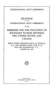
Hearings of the International Joint Commission in re remedies for the pollution of boundary waters between the United States and Canada
by International Joint Commission
English
1417h 39m read

Sewerage and Sewage Treatment
by Babbitt, Harold E. (Harold Eaton)
English
2636h 17m read

Rural Hygiene
by Ogden, Henry N. (Henry Neely)
English
1937h 25m read